- Digital Electronics - Home
- Digital Electronics Basics
- Types of Digital Systems
- Types of Signals
- Logic Levels And Pulse Waveforms
- Digital System Components
- Digital Logic Operations
- Digital Systems Advantages
- Number Systems
- Number Systems
- Binary Numbers Representation
- Binary Arithmetic
- Signed Binary Arithmetic
- Octal Arithmetic
- Hexadecimal Arithmetic
- Complement Arithmetic
- Base Conversions
- Base Conversions
- Binary to Decimal Conversion
- Decimal to Binary Conversion
- Binary to Octal Conversion
- Octal to Binary Conversion
- Octal to Decimal Conversion
- Decimal to Octal Conversion
- Hexadecimal to Binary Conversion
- Binary to Hexadecimal Conversion
- Hexadecimal to Decimal Conversion
- Decimal to Hexadecimal Conversion
- Octal to Hexadecimal Conversion
- Hexadecimal to Octal Conversion
- Binary Codes
- Binary Codes
- 8421 BCD Code
- Excess-3 Code
- Gray Code
- ASCII Codes
- EBCDIC Code
- Code Conversion
- Error Detection & Correction Codes
- Logic Gates
- Logic Gates
- AND Gate
- OR Gate
- NOT Gate
- Universal Gates
- XOR Gate
- XNOR Gate
- CMOS Logic Gate
- OR Gate Using Diode Resistor Logic
- AND Gate vs OR Gate
- Two Level Logic Realization
- Threshold Logic
- Boolean Algebra
- Boolean Algebra
- Laws of Boolean Algebra
- Boolean Functions
- DeMorgan's Theorem
- SOP and POS Form
- POS to Standard POS Form
- Minimization Techniques
- K-Map Minimization
- Three Variable K-Map
- Four Variable K-Map
- Five Variable K-Map
- Six Variable K-Map
- Don't Care Condition
- Quine-McCluskey Method
- Min Terms and Max Terms
- Canonical and Standard Form
- Max Term Representation
- Simplification using Boolean Algebra
- Combinational Logic Circuits
- Digital Combinational Circuits
- Digital Arithmetic Circuits
- Multiplexers
- Multiplexer Design Procedure
- Mux Universal Gate
- 2-Variable Function Using 4:1 Mux
- 3-Variable Function Using 8:1 Mux
- Demultiplexers
- Mux vs Demux
- Parity Bit Generator and Checker
- Comparators
- Encoders
- Keyboard Encoders
- Priority Encoders
- Decoders
- Arithmetic Logic Unit
- 7-Segment LED Display
- Code Converters
- Code Converters
- Binary to Decimal Converter
- Decimal to BCD Converter
- BCD to Decimal Converter
- Binary to Gray Code Converter
- Gray Code to Binary Converter
- BCD to Excess-3 Converter
- Excess-3 to BCD Converter
- Adders
- Half Adders
- Full Adders
- Serial Adders
- Parallel Adders
- Full Adder using Half Adder
- Half Adder vs Full Adder
- Full Adder with NAND Gates
- Half Adder with NAND Gates
- Binary Adder-Subtractor
- Subtractors
- Half Subtractors
- Full Subtractors
- Parallel Subtractors
- Full Subtractor using 2 Half Subtractors
- Half Subtractor using NAND Gates
- Sequential Logic Circuits
- Digital Sequential Circuits
- Clock Signal and Triggering
- Latches
- Shift Registers
- Shift Register Applications
- Binary Registers
- Bidirectional Shift Register
- Counters
- Binary Counters
- Non-binary Counter
- Design of Synchronous Counter
- Synchronous vs Asynchronous Counter
- Finite State Machines
- Algorithmic State Machines
- Flip Flops
- Flip-Flops
- Conversion of Flip-Flops
- D Flip-Flops
- JK Flip-Flops
- T Flip-Flops
- SR Flip-Flops
- Clocked SR Flip-Flop
- Unclocked SR Flip-Flop
- Clocked JK Flip-Flop
- JK to T Flip-Flop
- SR to JK Flip-Flop
- Triggering Methods:Flip-Flop
- Edge-Triggered Flip-Flop
- Master-Slave JK Flip-Flop
- Race-around Condition
- A/D and D/A Converters
- Analog-to-Digital Converter
- Digital-to-Analog Converter
- DAC and ADC ICs
- Realization of Logic Gates
- NOT Gate from NAND Gate
- OR Gate from NAND Gate
- AND Gate from NAND Gate
- NOR Gate from NAND Gate
- XOR Gate from NAND Gate
- XNOR Gate from NAND Gate
- NOT Gate from NOR Gate
- OR Gate from NOR Gate
- AND Gate from NOR Gate
- NAND Gate from NOR Gate
- XOR Gate from NOR Gate
- XNOR Gate from NOR Gate
- NAND/NOR Gate using CMOS
- Full Subtractor using NAND Gate
- AND Gate Using 2:1 MUX
- OR Gate Using 2:1 MUX
- NOT Gate Using 2:1 MUX
- Memory Devices
- Memory Devices
- RAM and ROM
- Cache Memory Design
- Programmable Logic Devices
- Programmable Logic Devices
- Programmable Logic Array
- Programmable Array Logic
- Field Programmable Gate Arrays
- Digital Electronics Families
- Digital Electronics Families
- CPU Architecture
- CPU Architecture
4 Variable K-Map in Digital Electronics
Several techniques have been developed to simplify a complex Boolean expression into its simplest form. K-Map or Karnaugh Map is one of such minimization or simplification techniques.
The K-Map or Karnaugh Map is a graph or chart which composed of an arrangement of adjacent cells. Where, each cell of the K-Map represents a particular combination of variables in either sum or product form. The K-map can be used to simplify Boolean functions involving any number of variables. But, the simplification of a Boolean function using K-map becomes tedious for problems involving five or more variables. Therefore, in actual practice, the K-map is limited to six variables.
The number of cells in a K-map depends upon the number of variables in the given Boolean function. A K-map will have 2n cells or squares, where n is the number of variables in the Boolean expression. Therefore, for a two variable function, the K-map will have 22 = 4 cells, for a three variable Boolean function, the K-map will have 23 = 8 cells, and for four variable Boolean function, the K-map will have 24 = 16 cells, and so on.
Here, we will discuss four variable K-Map and will use it to simplify Boolean functions in 4 variables.
Four Variable K-Map
A four variable K-map is used to simplify a complex Boolean expression in 4 variables. As we know, a four variable Boolean expression can have 24 = 16 possible combinations of variables.
For example, in SOP (Sum of Products) Form,
$$\mathrm{f(A,B,C,D) \: = \: \bar{A}\bar{B}\bar{C}\bar{D} \: + \: \bar{A}\bar{B}\bar{C}D \: + \: \bar{A}\bar{B}C\bar{D} \: + \: \dots \: + \: ABCD}$$
The minterm representation of this expression is as follows,
$$\mathrm{f(A,B,C,D) \: = \: m_{0} \: + \: m_{1} \: + \: m_{2} \: + \: \dotso \: + \: m_{15}}$$
In POS (Product of Sums) Form,
$$\mathrm{f(A,B,C,D) \: = \: (A \: + \: B \: + \: C \: + \: D)(A \: + \: B \: + \: C \: + \: \overline{D} )(A \: + \: B \: + \: \overline{C} \: + \: D) \: \dotso \: (\overline{A} \: + \: \overline{B} \: + \: \overline{C} \: + \: \overline{D})}$$
The maxterm representation of this expression is as,
$$\mathrm{f(A,B,C,D) \: = \: M_{0}\cdot M_{1}\cdot M_{2} \: \dotso \: M_{15}}$$
A 4 variable K-map has 16 cells, where each cell represents either a minterm or a maxterm of the function. The SOP (Sum of products) form and POS (Product of Sums) form of a four variable Boolean expression is shown in Figure 1.
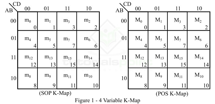
Here, the binary number designations of the columns and rows are in the Gray code. This is known as adjacent ordering. In these K-maps, the binary numbers along the left side of the map indicate the conditions of variables A and B along any row, and the binary numbers along the top of the K-map indicate the conditions of the variables C and D along any column. The decimal numbers in the bottom right corners of the cells indicate the minterm or maxterm designation.
Now, let us consider an example to illustrate the utilization of the 4 variable K-map for simplification of a Boolean function.
Example 1
Simplify the following Boolean expression using the 4-variable K-map.
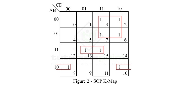
$$\mathrm{f \lgroup A,B,C,D \rgroup \: = \: \sum m \lgroup 2,3,6,7,8,10,13,15 \rgroup}$$
Solution
The SOP K-map representation of the given Boolean function is shown in Figure 2.
Explanation
The simplification of the function is done as per the following steps −
There are no isolated 1s in the K-Map.
The minterm m2 can form a 4-square with m3, m6, and m7. Make it and read it as −
$$\mathrm{\bar{A}C}()$$
The minterm m8 can form a 2-square with m10. Make it and read it as −
$$\mathrm{AB\bar{D}}()$$
The minterm m13 can form a 2-square with m15. Make it and read it as −
$$\mathrm{(A\bar{B}D)}$$
Write all the product in SOP form.
So the simplified SOP expression is,
$$\mathrm{f(A,B,C,D) \: = \: \bar{A}C \: + \: A\bar{B}D \: + \: AB\bar{D}}$$
Example 2
Minimize the following Boolean expression using the 4-variable K-map.
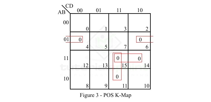
$$\mathrm{f(A,B,C,D) \: = \: \prod \: M(4,6,11,14,15)}$$
Solution
The POS K-map representation of the given Boolean function is shown in Figure 3.
Explanation
In minimization of the given function is done as per the following step −
There are no isolated zeros in the K-map.
The maxterm M4 can form a 2-squate with M6. Make it and read it as −
$$\mathrm{(A \: + \: \bar{B} \: + \: D)}$$
The maxterm M11 can form a 2-square with M15. Make it and read it as −
$$\mathrm{(\bar{A} \: + \: \bar{C} \: + \: \bar{D})}$$
Now, only maxterm M14 is left. M14 can form 2-square with M6 or M15. If we make it with M15, then read it as −
$$\mathrm{(\bar{A} \: + \: \bar{B} \: + \: \bar{C})}$$
Finally, write all the sum terms in POS form.
So, the reduced POS expression of the given Boolean function is,
$$\mathrm{f(A,B,C,D) \: = \: (A \: + \: \bar{B} \: + \: D)(\bar{A} \: + \: \bar{C} \: + \: \bar{D})(\bar{A} \: + \: \bar{B} \: + \: \bar{C})}$$
Numerical Problems on K-Map
Q1. Reduce the following Boolean function using 4-variable K-map
$$\mathrm{f \lgroup A,B,C,D \rgroup \: = \: \sum m \lgroup 0,1,2,5,8,10,11,13,14,15 \rgroup }$$
Q2. Minimize the following Boolean expression using 4-variable K-Map.
$$\mathrm{f \lgroup A,B,C,D \rgroup \: = \: \prod \: M \lgroup 0,2,8,10,11,13,15 \rgroup}$$
Conclusion
This is all about the 4 variable K-map and its application to minimize a Boolean expression into its minimal form. From the above discussion, we can conclude that the 4-variable K-map is a graphical representation of a Boolean expression involving 4 variables and is represented in standard SOP or POS form. This is used to convert a standard SOP or POS form, or minterm form or maxterm form of a 4-variable Boolean expression into its minimal SOP or POS form.