- Electrical Machines - Home
- Basic Concepts
- Electromechanical Energy Conversion
- Energy Stored in Magnetic Field
- Singly-Excited and Doubly Excited Systems
- Rotating Electrical Machines
- Electrical Machines Types
- Faraday’s Laws of Electromagnetic Induction
- Concept of Induced EMF
- Fleming's Left Hand and Right Hand Rules
- Transformers
- Electrical Transformer
- Construction of Transformer
- EMF Equation of Transformer
- Turns Ratio and Voltage Transformation Ratio
- Ideal Transformer
- Practical Transformer
- Ideal and Practical Transformers
- Transformer on DC
- Losses in a Transformer
- Efficiency of Transformer
- 3-Phase Transformer
- Types of Transformers
- More on Transformers
- Transformer Working Principle
- Single-Phase Transformer Working Principle
- 3-Phase Transformer Principle
- 3-Phase Induction Motor Torque-Slip
- 3-Phase Induction Motor Torque-Speed
- 3-Phase Transformer Harmonics
- Double-Star Connection (3-6 Phase)
- Double-delta Connection (3-6 Phase)
- Transformer Ratios
- Voltage Regulation
- Delta-Star Connection (3-Phase)
- Star-Delta Connection (3-Phase)
- Autotransformer Conversion
- Back-to-back Test (Sumpner's Test)
- Transformer Voltage Drop
- Autotransformer Output
- Open and Short Circuit Test
- 3-Phase Autotransformer
- Star-Star Connection
- 6-Phase Diametrical Connections
- Circuit Test (Three-Winding)
- Potential Transformer
- Transformers Parallel Operation
- Open Delta (V-V) Connection
- Autotransformer
- Current Transformer
- No-Load Current Wave
- Transformer Inrush Current
- Transformer Vector Groups
- 3 to 12-Phase Transformers
- Scott-T Transformer Connection
- Transformer kVA Rating
- Three-Winding Transformer
- Delta-Delta Connection Transformer
- Transformer DC Supply Issue
- Equivalent Circuit Transformer
- Simplified Equivalent Circuit of Transformer
- Transformer No-Load Condition
- Transformer Load Condition
- OTI WTI Transformer
- CVT Transformer
- Isolation vs Regular Transformer
- Dry vs Oil-Filled
- DC Machines
- Construction of DC Machines
- Types of DC Machines
- Working Principle of DC Generator
- EMF Equation of DC Generator
- Derivation of EMF Equation DC Generator
- Types of DC Generators
- Working Principle of DC Motor
- Back EMF in DC Motor
- Types of DC Motors
- Losses in DC Machines
- Applications of DC Machines
- More on DC Machines
- DC Generator
- DC Generator Armature Reaction
- DC Generator Commutator Action
- Stepper vs DC Motors
- DC Shunt Generators Critical Resistance
- DC Machines Commutation
- DC Motor Characteristics
- Synchronous Generator Working Principle
- DC Generator Characteristics
- DC Generator Demagnetizing & Cross-Magnetizing
- DC Motor Voltage & Power Equations
- DC Generator Efficiency
- Electric Breaking of DC Motors
- DC Motor Efficiency
- Four Quadrant Operation of DC Motors
- Open Circuit Characteristics of DC Generators
- Voltage Build-Up in Self-Excited DC Generators
- Types of Armature Winding in DC Machines
- Torque in DC Motors
- Swinburne’s Test of DC Machine
- Speed Control of DC Shunt Motor
- Speed Control of DC Series Motor
- DC Motor of Speed Regulation
- Hopkinson's Test
- Permanent Magnet DC Motor
- Permanent Magnet Stepper Motor
- DC Servo Motor Theory
- DC Series vs Shunt Motor
- BLDC Motor vs PMSM Motor
- Induction Motors
- Introduction to Induction Motor
- Single-Phase Induction Motor
- 3-Phase Induction Motor
- Construction of 3-Phase Induction Motor
- 3-Phase Induction Motor on Load
- Characteristics of 3-Phase Induction Motor
- Speed Regulation and Speed Control
- Methods of Starting 3-Phase Induction Motors
- More on Induction Motors
- 3-Phase Induction Motor Working Principle
- 3-Phase Induction Motor Rotor Parameters
- Double Cage Induction Motor Equivalent Circuit
- Induction Motor Equivalent Circuit Models
- Slip Ring vs Squirrel Cage Induction Motors
- Single-Cage vs Double-Cage Induction Motor
- Induction Motor Equivalent Circuits
- Induction Motor Crawling & Cogging
- Induction Motor Blocked Rotor Test
- Induction Motor Circle Diagram
- 3-Phase Induction Motors Applications
- 3-Phase Induction Motors Torque Ratios
- Induction Motors Power Flow Diagram & Losses
- Determining Induction Motor Efficiency
- Induction Motor Speed Control by Pole-Amplitude Modulation
- Induction Motor Inverted or Rotor Fed
- High Torque Cage Motors
- Double-Cage Induction Motor Torque-Slip Characteristics
- 3-Phase Induction Motors Starting Torque
- 3-phase Induction Motor - Rotor Resistance Starter
- 3-phase Induction Motor Running Torque
- 3-Phase Induction Motor - Rotating Magnetic Field
- Isolated Induction Generator
- Capacitor-Start Induction Motor
- Capacitor-Start Capacitor-Run Induction Motor
- Winding EMFs in 3-Phase Induction Motors
- Split-Phase Induction Motor
- Shaded Pole Induction Motor
- Repulsion-Start Induction-Run Motor
- Repulsion Induction Motor
- PSC Induction Motor
- Single-Phase Induction Motor Performance Analysis
- Linear Induction Motor
- Single-Phase Induction Motor Testing
- 3-Phase Induction Motor Fault Types
- Synchronous Machines
- Introduction to 3-Phase Synchronous Machines
- Construction of Synchronous Machine
- Working of 3-Phase Alternator
- Armature Reaction in Synchronous Machines
- Output Power of 3-Phase Alternator
- Losses and Efficiency of an Alternator
- Losses and Efficiency of 3-Phase Alternator
- Working of 3-Phase Synchronous Motor
- Equivalent Circuit and Power Factor of Synchronous Motor
- Power Developed by Synchronous Motor
- More on Synchronous Machines
- AC Motor Types
- Induction Generator (Asynchronous Generator)
- Synchronous Speed Slip of 3-Phase Induction Motor
- Armature Reaction in Alternator at Leading Power Factor
- Armature Reaction in Alternator at Lagging Power Factor
- Stationary Armature vs Rotating Field Alternator Advantages
- Synchronous Impedance Method for Voltage Regulation
- Saturated & Unsaturated Synchronous Reactance
- Synchronous Reactance & Impedance
- Significance of Short Circuit Ratio in Alternator
- Hunting Effect Alternator
- Hydrogen Cooling in Synchronous Generators
- Excitation System of Synchronous Machine
- Equivalent Circuit Phasor Diagram of Synchronous Generator
- EMF Equation of Synchronous Generator
- Cooling Methods for Synchronous Generators
- Assumptions in Synchronous Impedance Method
- Armature Reaction at Unity Power Factor
- Voltage Regulation of Alternator
- Synchronous Generator with Infinite Bus Operation
- Zero Power Factor of Synchronous Generator
- Short Circuit Ratio Calculation of Synchronous Machines
- Speed-Frequency Relationship in Alternator
- Pitch Factor in Alternator
- Max Reactive Power in Synchronous Generators
- Power Flow Equations for Synchronous Generator
- Potier Triangle for Voltage Regulation in Alternators
- Parallel Operation of Alternators
- Load Sharing in Parallel Alternators
- Slip Test on Synchronous Machine
- Constant Flux Linkage Theorem
- Blondel's Two Reaction Theory
- Synchronous Machine Oscillations
- Ampere Turn Method for Voltage Regulation
- Salient Pole Synchronous Machine Theory
- Synchronization by Synchroscope
- Synchronization by Synchronizing Lamp Method
- Sudden Short Circuit in 3-Phase Alternator
- Short Circuit Transient in Synchronous Machines
- Power-Angle of Salient Pole Machines
- Prime-Mover Governor Characteristics
- Power Input of Synchronous Generator
- Power Output of Synchronous Generator
- Power Developed by Salient Pole Motor
- Phasor Diagrams of Cylindrical Rotor Moto
- Synchronous Motor Excitation Voltage Determination
- Hunting Synchronous Motor
- Self-Starting Synchronous Motor
- Unidirectional Torque Production in Synchronous Motor
- Effect of Load Change on Synchronous Motor
- Field Excitation Effect on Synchronous Motor
- Output Power of Synchronous Motor
- Input Power of Synchronous Motor
- V Curves & Inverted V Curves of Synchronous Motor
- Torque in Synchronous Motor
- Construction of 3-Phase Synchronous Motor
- Synchronous Motor
- Synchronous Condenser
- Power Flow in Synchronous Motor
- Types of Faults in Alternator
- Miscellaneous Topics
- Electrical Generator
- Determining Electric Motor Load
- Solid State Motor Starters
- Characteristics of Single-Phase Motor
- Types of AC Generators
- Three-Point Starter
- Four-Point Starter
- Ward Leonard Speed Control Method
- Pole Changing Method
- Stator Voltage Control Method
- DOL Starter
- Star-Delta Starter
- Hysteresis Motor
- 2-Phase & 3-Phase AC Servo Motors
- Repulsion Motor
- Reluctance Motor
- Stepper Motor
- PCB Motor
- Single-Stack Variable Reluctance Stepper Motor
- Schrage Motor
- Hybrid Schrage Motor
- Multi-Stack Variable Reluctance Stepper Motor
- Universal Motor
- Step Angle in Stepper Motor
- Stepper Motor Torque-Pulse Rate Characteristics
- Distribution Factor
- Electrical Machines Basic Terms
- Synchronizing Torque Coefficient
- Synchronizing Power Coefficient
- Metadyne
- Motor Soft Starter
- CVT vs PT
- Metering CT vs Protection CT
- Stator and Rotor in Electrical Machines
- Electric Motor Winding
- Electric Motor
- Useful Resources
- Quick Guide
- Resources
- Discussion
Armature Reaction in DC Generator
Armature Reaction
The current flowing through the armature conductors creates a magnetic field, which is called as armature flux. This armature flux distorts and weakens the magnetic flux produced by the main poles. This effect of armature flux on the main flux is known as armature reaction.
Case 1
Consider a two pole generator on no-load. Thus, the current in the armature conductors is zero. Under this condition, there is only the main flux (φm) in the machine which is produced by the main poles. This main flux is distributed symmetrically with respect to the polar axis (i.e. centre line of field poles).

The magnetic neutral axis (MNA, which is a plane perpendicular to the axis of flux) coincides with the geometrical neutral axis (GNA). The brushes are always placed along MNA, hence the MNA is also called as axis of commutation.
Case 2
Now consider the armature carrying current with no current in the field coils. The direction of flux produced by the current in the armature conductors may be determined by cork-screw rule. Refer the figure, the conductors under the N-pole carry current in the direction into the plane of paper. Thus, the flux produced by the conductors under the N-pole is in the downward direction.

Similarly, the conductors under the S-pole carry current in the direction out of the plane of paper. These conductors also produce a flux which is directed downward. Therefore, all the armature conductor produces a flux through the armature in the downward direction. This flux is known as armature flux (φA).
Case 3
This case shows the condition when the field current and armature currents are acting simultaneously. Hence, there are two fluxes inside the machine, one is produced by the main field poles of the generator and the other by the current in the armature conductors. These two fluxes combine to give a resultant flux (φR).
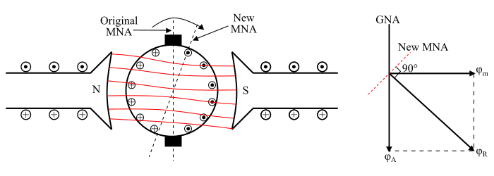
From the above discussion, it can be seen that the main flux entering the armature is shifted and distorted. The distortion increases the flux density in the upper pole tip of the N-pole and in the lower pole tip of the S-pole. Similarly, there is a decrease in the flux density in the lower pole tip of the N-pole and in the upper pole tip of the S-pole. Therefore, the direction of the resultant flux has shifted in the direction of rotation of the generator.
Since the MNA is always perpendicular to the axis of the resultant flux, hence the MNA is also shifted. Due to the non-linear behaviour and saturation of the core, the increase in the flux in one pole tip is less than the decrease in the flux in the other pole tip. This results in, the main flux is decreased. Consequently, the generated emf (Eg ∝ Nφm) is decreased with the increase in load.
Effects of Armature Reaction
The armature reaction in a DC generator causes the following adverse effects
- As the total field flux produced by each pole is slightly reduced, which reduces the generated EMF.
- Due to the shifting of the resultant flux axis, the MNA is also shifted in the direction of rotation of the generator.
- Due to the armature reaction, a flux is established in the commutating zone or neutral zone. This flux in the neutral zone induces conductor voltage that causes the commutation problems.
Remedies to the Armature Reaction Effect
There are four methods to reduce the armature reaction problem
Adjust the Brush Position
In this method, rotate the brush mechanism to find the correct neutral zone position. This can be applied only fixed load current.
Modify the Ends of the Poles
In this method, the field pole tip is to be modified so that high flux cannot exist on the ends because of the high reluctance path.
Interpoles
The effect of armature reaction can be reduced by placing a set of interpoles or commutating poles between the main poles of the DC generator. The polarity of interpole must be that of the main pole just next of it in the direction of rotation. The interpole windings are connected in series with the armature so that respective fluxes rise and fall together with the changes in the load current.
Compensating Winding
The heavy duty operations produce very sudden changes in the armature reaction. In such generators, the interpoles do not adequately neutralise the armature flux. Hence, to overcome this problem, the compensating windings are used.
The compensating winding is an auxiliary winding embedded in the slots of the main poles. The compensating winding is connected in series with the armature in such a way that the direction of the current in the compensating conductors in any one pole face will be opposite to the direction of current through the adjacent armature conductors. Hence, the compensating windings produce a flux equal and opposite to the armature flux and thus completely neutralise the armature reaction.