- Electrical Machines - Home
- Basic Concepts
- Electromechanical Energy Conversion
- Energy Stored in Magnetic Field
- Singly-Excited and Doubly Excited Systems
- Rotating Electrical Machines
- Electrical Machines Types
- Faraday’s Laws of Electromagnetic Induction
- Concept of Induced EMF
- Fleming's Left Hand and Right Hand Rules
- Transformers
- Electrical Transformer
- Construction of Transformer
- EMF Equation of Transformer
- Turns Ratio and Voltage Transformation Ratio
- Ideal Transformer
- Practical Transformer
- Ideal and Practical Transformers
- Transformer on DC
- Losses in a Transformer
- Efficiency of Transformer
- 3-Phase Transformer
- Types of Transformers
- More on Transformers
- Transformer Working Principle
- Single-Phase Transformer Working Principle
- 3-Phase Transformer Principle
- 3-Phase Induction Motor Torque-Slip
- 3-Phase Induction Motor Torque-Speed
- 3-Phase Transformer Harmonics
- Double-Star Connection (3-6 Phase)
- Double-delta Connection (3-6 Phase)
- Transformer Ratios
- Voltage Regulation
- Delta-Star Connection (3-Phase)
- Star-Delta Connection (3-Phase)
- Autotransformer Conversion
- Back-to-back Test (Sumpner's Test)
- Transformer Voltage Drop
- Autotransformer Output
- Open and Short Circuit Test
- 3-Phase Autotransformer
- Star-Star Connection
- 6-Phase Diametrical Connections
- Circuit Test (Three-Winding)
- Potential Transformer
- Transformers Parallel Operation
- Open Delta (V-V) Connection
- Autotransformer
- Current Transformer
- No-Load Current Wave
- Transformer Inrush Current
- Transformer Vector Groups
- 3 to 12-Phase Transformers
- Scott-T Transformer Connection
- Transformer kVA Rating
- Three-Winding Transformer
- Delta-Delta Connection Transformer
- Transformer DC Supply Issue
- Equivalent Circuit Transformer
- Simplified Equivalent Circuit of Transformer
- Transformer No-Load Condition
- Transformer Load Condition
- OTI WTI Transformer
- CVT Transformer
- Isolation vs Regular Transformer
- Dry vs Oil-Filled
- DC Machines
- Construction of DC Machines
- Types of DC Machines
- Working Principle of DC Generator
- EMF Equation of DC Generator
- Derivation of EMF Equation DC Generator
- Types of DC Generators
- Working Principle of DC Motor
- Back EMF in DC Motor
- Types of DC Motors
- Losses in DC Machines
- Applications of DC Machines
- More on DC Machines
- DC Generator
- DC Generator Armature Reaction
- DC Generator Commutator Action
- Stepper vs DC Motors
- DC Shunt Generators Critical Resistance
- DC Machines Commutation
- DC Motor Characteristics
- Synchronous Generator Working Principle
- DC Generator Characteristics
- DC Generator Demagnetizing & Cross-Magnetizing
- DC Motor Voltage & Power Equations
- DC Generator Efficiency
- Electric Breaking of DC Motors
- DC Motor Efficiency
- Four Quadrant Operation of DC Motors
- Open Circuit Characteristics of DC Generators
- Voltage Build-Up in Self-Excited DC Generators
- Types of Armature Winding in DC Machines
- Torque in DC Motors
- Swinburne’s Test of DC Machine
- Speed Control of DC Shunt Motor
- Speed Control of DC Series Motor
- DC Motor of Speed Regulation
- Hopkinson's Test
- Permanent Magnet DC Motor
- Permanent Magnet Stepper Motor
- DC Servo Motor Theory
- DC Series vs Shunt Motor
- BLDC Motor vs PMSM Motor
- Induction Motors
- Introduction to Induction Motor
- Single-Phase Induction Motor
- 3-Phase Induction Motor
- Construction of 3-Phase Induction Motor
- 3-Phase Induction Motor on Load
- Characteristics of 3-Phase Induction Motor
- Speed Regulation and Speed Control
- Methods of Starting 3-Phase Induction Motors
- More on Induction Motors
- 3-Phase Induction Motor Working Principle
- 3-Phase Induction Motor Rotor Parameters
- Double Cage Induction Motor Equivalent Circuit
- Induction Motor Equivalent Circuit Models
- Slip Ring vs Squirrel Cage Induction Motors
- Single-Cage vs Double-Cage Induction Motor
- Induction Motor Equivalent Circuits
- Induction Motor Crawling & Cogging
- Induction Motor Blocked Rotor Test
- Induction Motor Circle Diagram
- 3-Phase Induction Motors Applications
- 3-Phase Induction Motors Torque Ratios
- Induction Motors Power Flow Diagram & Losses
- Determining Induction Motor Efficiency
- Induction Motor Speed Control by Pole-Amplitude Modulation
- Induction Motor Inverted or Rotor Fed
- High Torque Cage Motors
- Double-Cage Induction Motor Torque-Slip Characteristics
- 3-Phase Induction Motors Starting Torque
- 3-phase Induction Motor - Rotor Resistance Starter
- 3-phase Induction Motor Running Torque
- 3-Phase Induction Motor - Rotating Magnetic Field
- Isolated Induction Generator
- Capacitor-Start Induction Motor
- Capacitor-Start Capacitor-Run Induction Motor
- Winding EMFs in 3-Phase Induction Motors
- Split-Phase Induction Motor
- Shaded Pole Induction Motor
- Repulsion-Start Induction-Run Motor
- Repulsion Induction Motor
- PSC Induction Motor
- Single-Phase Induction Motor Performance Analysis
- Linear Induction Motor
- Single-Phase Induction Motor Testing
- 3-Phase Induction Motor Fault Types
- Synchronous Machines
- Introduction to 3-Phase Synchronous Machines
- Construction of Synchronous Machine
- Working of 3-Phase Alternator
- Armature Reaction in Synchronous Machines
- Output Power of 3-Phase Alternator
- Losses and Efficiency of an Alternator
- Losses and Efficiency of 3-Phase Alternator
- Working of 3-Phase Synchronous Motor
- Equivalent Circuit and Power Factor of Synchronous Motor
- Power Developed by Synchronous Motor
- More on Synchronous Machines
- AC Motor Types
- Induction Generator (Asynchronous Generator)
- Synchronous Speed Slip of 3-Phase Induction Motor
- Armature Reaction in Alternator at Leading Power Factor
- Armature Reaction in Alternator at Lagging Power Factor
- Stationary Armature vs Rotating Field Alternator Advantages
- Synchronous Impedance Method for Voltage Regulation
- Saturated & Unsaturated Synchronous Reactance
- Synchronous Reactance & Impedance
- Significance of Short Circuit Ratio in Alternator
- Hunting Effect Alternator
- Hydrogen Cooling in Synchronous Generators
- Excitation System of Synchronous Machine
- Equivalent Circuit Phasor Diagram of Synchronous Generator
- EMF Equation of Synchronous Generator
- Cooling Methods for Synchronous Generators
- Assumptions in Synchronous Impedance Method
- Armature Reaction at Unity Power Factor
- Voltage Regulation of Alternator
- Synchronous Generator with Infinite Bus Operation
- Zero Power Factor of Synchronous Generator
- Short Circuit Ratio Calculation of Synchronous Machines
- Speed-Frequency Relationship in Alternator
- Pitch Factor in Alternator
- Max Reactive Power in Synchronous Generators
- Power Flow Equations for Synchronous Generator
- Potier Triangle for Voltage Regulation in Alternators
- Parallel Operation of Alternators
- Load Sharing in Parallel Alternators
- Slip Test on Synchronous Machine
- Constant Flux Linkage Theorem
- Blondel's Two Reaction Theory
- Synchronous Machine Oscillations
- Ampere Turn Method for Voltage Regulation
- Salient Pole Synchronous Machine Theory
- Synchronization by Synchroscope
- Synchronization by Synchronizing Lamp Method
- Sudden Short Circuit in 3-Phase Alternator
- Short Circuit Transient in Synchronous Machines
- Power-Angle of Salient Pole Machines
- Prime-Mover Governor Characteristics
- Power Input of Synchronous Generator
- Power Output of Synchronous Generator
- Power Developed by Salient Pole Motor
- Phasor Diagrams of Cylindrical Rotor Moto
- Synchronous Motor Excitation Voltage Determination
- Hunting Synchronous Motor
- Self-Starting Synchronous Motor
- Unidirectional Torque Production in Synchronous Motor
- Effect of Load Change on Synchronous Motor
- Field Excitation Effect on Synchronous Motor
- Output Power of Synchronous Motor
- Input Power of Synchronous Motor
- V Curves & Inverted V Curves of Synchronous Motor
- Torque in Synchronous Motor
- Construction of 3-Phase Synchronous Motor
- Synchronous Motor
- Synchronous Condenser
- Power Flow in Synchronous Motor
- Types of Faults in Alternator
- Miscellaneous Topics
- Electrical Generator
- Determining Electric Motor Load
- Solid State Motor Starters
- Characteristics of Single-Phase Motor
- Types of AC Generators
- Three-Point Starter
- Four-Point Starter
- Ward Leonard Speed Control Method
- Pole Changing Method
- Stator Voltage Control Method
- DOL Starter
- Star-Delta Starter
- Hysteresis Motor
- 2-Phase & 3-Phase AC Servo Motors
- Repulsion Motor
- Reluctance Motor
- Stepper Motor
- PCB Motor
- Single-Stack Variable Reluctance Stepper Motor
- Schrage Motor
- Hybrid Schrage Motor
- Multi-Stack Variable Reluctance Stepper Motor
- Universal Motor
- Step Angle in Stepper Motor
- Stepper Motor Torque-Pulse Rate Characteristics
- Distribution Factor
- Electrical Machines Basic Terms
- Synchronizing Torque Coefficient
- Synchronizing Power Coefficient
- Metadyne
- Motor Soft Starter
- CVT vs PT
- Metering CT vs Protection CT
- Stator and Rotor in Electrical Machines
- Electric Motor Winding
- Electric Motor
- Useful Resources
- Quick Guide
- Resources
- Discussion
Working of 3-Phase Synchronous Motor
A three-phase synchronous machine which converts three-phase electrical energy into mechanical energy is called a three-phase synchronous motor.
A three-phase synchronous motor is a constant speed machine, and it runs at the synchronous speed. The synchronous speed of a three-phase synchronous motor is given by,
$$\mathrm{\mathit{N_{s}}\:=\:\frac{120\mathit{f}}{\mathit{p}}\cdot \cdot \cdot (1)}$$
Where,f is the supply frequency andP is the number of field poles in the motor.
Like any other electric motor, a 3-phase synchronous motor also consists of two main parts namely stator and rotor. The stator houses a 3-phase armature winding and receives power from a 3-phase ac supply source. The rotor is a rotating part and carries field winding which is excited from an external source of DC power.
The most important drawback of a synchronous motor is that it is not self-starting and therefore an auxiliary mean has to be used for starting it.
Working of 3-Phase Synchronous Motor
Consider a three-phase synchronous motor having a salient-pole type rotor of two poles namely $\mathit{N_{\mathrm{2}}}$ and $\mathit{S_{\mathrm{2}}}$. Thus, the stator will also be wound for two poles which are $\mathit{N_{\mathrm{1}}}$ and $\mathit{S_{\mathrm{1}}}$. A direct voltage is applied to the rotor winding and a balanced three-phase ac voltage to the stator winding.
The stator winding produces a rotating magnetic field which revolves around the stator at a speed called synchronous speed ($\mathit{N_{\mathit{s}}}$).The direct current flowing through the rotor winding produces two field poles in the rotor and the magnetic field due to these poles is stationary so long as the rotor is not running. Hence, in this case we have a pair of revolving armature poles $\left ( \mathit{N_{\mathrm{1}}}-\mathit{S_{\mathrm{1}}} \right )$ and a pair of stationary rotor poles $\left ( \mathit{N_{\mathrm{2}}}-\mathit{S_{\mathrm{2}}} \right )$.
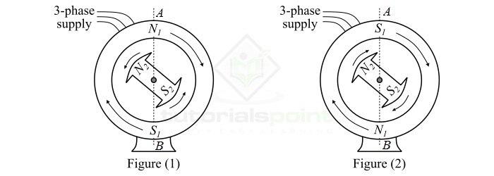
Now, consider an instant at which the stator poles are at positions A and B as shown in Figure-1. It is clear that poles $\mathit{N_{\mathrm{1}}}$ and $\mathit{N_{\mathrm{2}}}$ repel each other and so do the poles $\mathit{S_{\mathrm{1}}}$ and $\mathit{S_{\mathrm{1}}}$. Thus, the rotor tends to rotate in the anticlockwise direction. After a period of half-cycle of AC supply, the polarities of stator poles are reversed, but the polarities of the rotor poles remain the same as shown in Figure-2. In this situation, poles $\mathit{S_{\mathrm{1}}}$ and $\mathit{N_{\mathrm{2}}}$ attract each other and so do the poles $\mathit{N_{\mathrm{1}}}$ and $\mathit{S_{\mathrm{2}}}$. Thus, the rotor now tends to rotate in the clockwise direction.
Since, the stator poles are changing their polarities rapidly, they tend to pull the rotor first in one direction and after half-cycle of ac in the other direction. Because of the bidirectional torque on the rotor and high inertia of the rotor, the synchronous motor fails to start. Therefore, a synchronous motor has no self-starting torque.
Making a Synchronous Motor Self-Starting
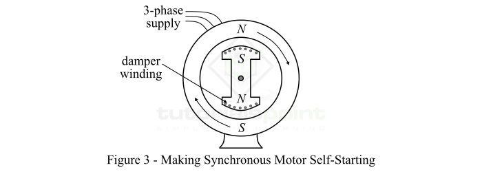
A synchronous motor cannot start by itself. To make the motor self-starting, a squirrel-cage winding, called damper winding, is provided on the rotor. The damper winding consists of copper bars embedded in the slots cut on in the pole faces of the salient poles of the rotor, as shown in Figure-3.
These damper windings serve to start the synchronous motor by itself, which is explained below −
Initially, a 3-phase supply is fed to the stator winding while the rotor winding is left open. The rotating magnetic field of the stator winding induces currents in the damper windings, and due to electromagnetic forces, the rotor starts moving. Thus, the synchronous motor is started as an induction motor.
Once the motor attains a speed nearly equal to the synchronous speed, the rotor winding is excited from a source of dc supply. Now, the resulting poles on the rotor face the stators pole of opposite polarity, and a strong magnetic attraction is set up between them. Thus, the rotor poles are locked with the rotating poles of the stator. Consequently, the rotor revolves at the same speed of the stator poles, i.e. synchronous speed.
Since the rotor is now rotating at the same speed as the stator field, the damper bars do not cut any flux, hence have no induced currents in them. Thus, the damper windings of the rotor are, in effect, removed from the operation of the motor.
In this way, a synchronous motor is made self-starting. It must be noted that due to magnetic interlocking between the stator and rotor poles, the synchronous motor can only run at synchronous speed.