- Electrical Machines - Home
- Basic Concepts
- Electromechanical Energy Conversion
- Energy Stored in Magnetic Field
- Singly-Excited and Doubly Excited Systems
- Rotating Electrical Machines
- Electrical Machines Types
- Faraday’s Laws of Electromagnetic Induction
- Concept of Induced EMF
- Fleming's Left Hand and Right Hand Rules
- Transformers
- Electrical Transformer
- Construction of Transformer
- EMF Equation of Transformer
- Turns Ratio and Voltage Transformation Ratio
- Ideal Transformer
- Practical Transformer
- Ideal and Practical Transformers
- Transformer on DC
- Losses in a Transformer
- Efficiency of Transformer
- 3-Phase Transformer
- Types of Transformers
- More on Transformers
- Transformer Working Principle
- Single-Phase Transformer Working Principle
- 3-Phase Transformer Principle
- 3-Phase Induction Motor Torque-Slip
- 3-Phase Induction Motor Torque-Speed
- 3-Phase Transformer Harmonics
- Double-Star Connection (3-6 Phase)
- Double-delta Connection (3-6 Phase)
- Transformer Ratios
- Voltage Regulation
- Delta-Star Connection (3-Phase)
- Star-Delta Connection (3-Phase)
- Autotransformer Conversion
- Back-to-back Test (Sumpner's Test)
- Transformer Voltage Drop
- Autotransformer Output
- Open and Short Circuit Test
- 3-Phase Autotransformer
- Star-Star Connection
- 6-Phase Diametrical Connections
- Circuit Test (Three-Winding)
- Potential Transformer
- Transformers Parallel Operation
- Open Delta (V-V) Connection
- Autotransformer
- Current Transformer
- No-Load Current Wave
- Transformer Inrush Current
- Transformer Vector Groups
- 3 to 12-Phase Transformers
- Scott-T Transformer Connection
- Transformer kVA Rating
- Three-Winding Transformer
- Delta-Delta Connection Transformer
- Transformer DC Supply Issue
- Equivalent Circuit Transformer
- Simplified Equivalent Circuit of Transformer
- Transformer No-Load Condition
- Transformer Load Condition
- OTI WTI Transformer
- CVT Transformer
- Isolation vs Regular Transformer
- Dry vs Oil-Filled
- DC Machines
- Construction of DC Machines
- Types of DC Machines
- Working Principle of DC Generator
- EMF Equation of DC Generator
- Derivation of EMF Equation DC Generator
- Types of DC Generators
- Working Principle of DC Motor
- Back EMF in DC Motor
- Types of DC Motors
- Losses in DC Machines
- Applications of DC Machines
- More on DC Machines
- DC Generator
- DC Generator Armature Reaction
- DC Generator Commutator Action
- Stepper vs DC Motors
- DC Shunt Generators Critical Resistance
- DC Machines Commutation
- DC Motor Characteristics
- Synchronous Generator Working Principle
- DC Generator Characteristics
- DC Generator Demagnetizing & Cross-Magnetizing
- DC Motor Voltage & Power Equations
- DC Generator Efficiency
- Electric Breaking of DC Motors
- DC Motor Efficiency
- Four Quadrant Operation of DC Motors
- Open Circuit Characteristics of DC Generators
- Voltage Build-Up in Self-Excited DC Generators
- Types of Armature Winding in DC Machines
- Torque in DC Motors
- Swinburne’s Test of DC Machine
- Speed Control of DC Shunt Motor
- Speed Control of DC Series Motor
- DC Motor of Speed Regulation
- Hopkinson's Test
- Permanent Magnet DC Motor
- Permanent Magnet Stepper Motor
- DC Servo Motor Theory
- DC Series vs Shunt Motor
- BLDC Motor vs PMSM Motor
- Induction Motors
- Introduction to Induction Motor
- Single-Phase Induction Motor
- 3-Phase Induction Motor
- Construction of 3-Phase Induction Motor
- 3-Phase Induction Motor on Load
- Characteristics of 3-Phase Induction Motor
- Speed Regulation and Speed Control
- Methods of Starting 3-Phase Induction Motors
- More on Induction Motors
- 3-Phase Induction Motor Working Principle
- 3-Phase Induction Motor Rotor Parameters
- Double Cage Induction Motor Equivalent Circuit
- Induction Motor Equivalent Circuit Models
- Slip Ring vs Squirrel Cage Induction Motors
- Single-Cage vs Double-Cage Induction Motor
- Induction Motor Equivalent Circuits
- Induction Motor Crawling & Cogging
- Induction Motor Blocked Rotor Test
- Induction Motor Circle Diagram
- 3-Phase Induction Motors Applications
- 3-Phase Induction Motors Torque Ratios
- Induction Motors Power Flow Diagram & Losses
- Determining Induction Motor Efficiency
- Induction Motor Speed Control by Pole-Amplitude Modulation
- Induction Motor Inverted or Rotor Fed
- High Torque Cage Motors
- Double-Cage Induction Motor Torque-Slip Characteristics
- 3-Phase Induction Motors Starting Torque
- 3-phase Induction Motor - Rotor Resistance Starter
- 3-phase Induction Motor Running Torque
- 3-Phase Induction Motor - Rotating Magnetic Field
- Isolated Induction Generator
- Capacitor-Start Induction Motor
- Capacitor-Start Capacitor-Run Induction Motor
- Winding EMFs in 3-Phase Induction Motors
- Split-Phase Induction Motor
- Shaded Pole Induction Motor
- Repulsion-Start Induction-Run Motor
- Repulsion Induction Motor
- PSC Induction Motor
- Single-Phase Induction Motor Performance Analysis
- Linear Induction Motor
- Single-Phase Induction Motor Testing
- 3-Phase Induction Motor Fault Types
- Synchronous Machines
- Introduction to 3-Phase Synchronous Machines
- Construction of Synchronous Machine
- Working of 3-Phase Alternator
- Armature Reaction in Synchronous Machines
- Output Power of 3-Phase Alternator
- Losses and Efficiency of an Alternator
- Losses and Efficiency of 3-Phase Alternator
- Working of 3-Phase Synchronous Motor
- Equivalent Circuit and Power Factor of Synchronous Motor
- Power Developed by Synchronous Motor
- More on Synchronous Machines
- AC Motor Types
- Induction Generator (Asynchronous Generator)
- Synchronous Speed Slip of 3-Phase Induction Motor
- Armature Reaction in Alternator at Leading Power Factor
- Armature Reaction in Alternator at Lagging Power Factor
- Stationary Armature vs Rotating Field Alternator Advantages
- Synchronous Impedance Method for Voltage Regulation
- Saturated & Unsaturated Synchronous Reactance
- Synchronous Reactance & Impedance
- Significance of Short Circuit Ratio in Alternator
- Hunting Effect Alternator
- Hydrogen Cooling in Synchronous Generators
- Excitation System of Synchronous Machine
- Equivalent Circuit Phasor Diagram of Synchronous Generator
- EMF Equation of Synchronous Generator
- Cooling Methods for Synchronous Generators
- Assumptions in Synchronous Impedance Method
- Armature Reaction at Unity Power Factor
- Voltage Regulation of Alternator
- Synchronous Generator with Infinite Bus Operation
- Zero Power Factor of Synchronous Generator
- Short Circuit Ratio Calculation of Synchronous Machines
- Speed-Frequency Relationship in Alternator
- Pitch Factor in Alternator
- Max Reactive Power in Synchronous Generators
- Power Flow Equations for Synchronous Generator
- Potier Triangle for Voltage Regulation in Alternators
- Parallel Operation of Alternators
- Load Sharing in Parallel Alternators
- Slip Test on Synchronous Machine
- Constant Flux Linkage Theorem
- Blondel's Two Reaction Theory
- Synchronous Machine Oscillations
- Ampere Turn Method for Voltage Regulation
- Salient Pole Synchronous Machine Theory
- Synchronization by Synchroscope
- Synchronization by Synchronizing Lamp Method
- Sudden Short Circuit in 3-Phase Alternator
- Short Circuit Transient in Synchronous Machines
- Power-Angle of Salient Pole Machines
- Prime-Mover Governor Characteristics
- Power Input of Synchronous Generator
- Power Output of Synchronous Generator
- Power Developed by Salient Pole Motor
- Phasor Diagrams of Cylindrical Rotor Moto
- Synchronous Motor Excitation Voltage Determination
- Hunting Synchronous Motor
- Self-Starting Synchronous Motor
- Unidirectional Torque Production in Synchronous Motor
- Effect of Load Change on Synchronous Motor
- Field Excitation Effect on Synchronous Motor
- Output Power of Synchronous Motor
- Input Power of Synchronous Motor
- V Curves & Inverted V Curves of Synchronous Motor
- Torque in Synchronous Motor
- Construction of 3-Phase Synchronous Motor
- Synchronous Motor
- Synchronous Condenser
- Power Flow in Synchronous Motor
- Types of Faults in Alternator
- Miscellaneous Topics
- Electrical Generator
- Determining Electric Motor Load
- Solid State Motor Starters
- Characteristics of Single-Phase Motor
- Types of AC Generators
- Three-Point Starter
- Four-Point Starter
- Ward Leonard Speed Control Method
- Pole Changing Method
- Stator Voltage Control Method
- DOL Starter
- Star-Delta Starter
- Hysteresis Motor
- 2-Phase & 3-Phase AC Servo Motors
- Repulsion Motor
- Reluctance Motor
- Stepper Motor
- PCB Motor
- Single-Stack Variable Reluctance Stepper Motor
- Schrage Motor
- Hybrid Schrage Motor
- Multi-Stack Variable Reluctance Stepper Motor
- Universal Motor
- Step Angle in Stepper Motor
- Stepper Motor Torque-Pulse Rate Characteristics
- Distribution Factor
- Electrical Machines Basic Terms
- Synchronizing Torque Coefficient
- Synchronizing Power Coefficient
- Metadyne
- Motor Soft Starter
- CVT vs PT
- Metering CT vs Protection CT
- Stator and Rotor in Electrical Machines
- Electric Motor Winding
- Electric Motor
- Useful Resources
- Quick Guide
- Resources
- Discussion
Scott-T Transformer Connection
The Scott-T connection is a method of connecting two 1-phase transformers to perform the 3- phase to 2-phase conversion and vice-versa. In the Scott connection, the two 1-phase transformers are connected electrically (not magnetically), where one transformer is known as main transformer and the other is called as auxiliary or teaser transformer.
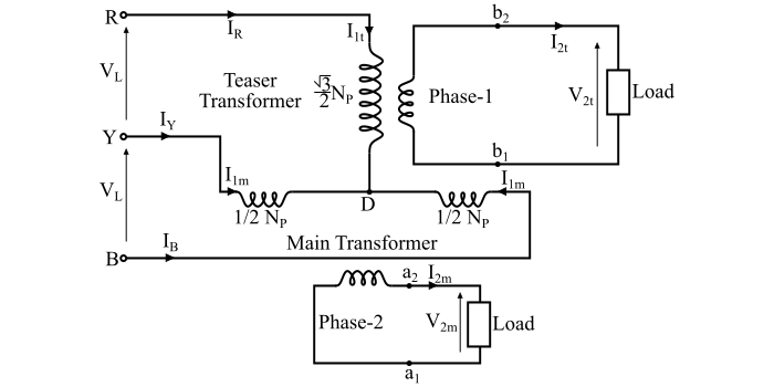
The connection diagram of the Scott connection is shown in the figure. The main transformer is the centre tapped transformer at point D and is connected across the lines Y and B of the 3- phase side. Thus, the primary of the main transformer is YB and the secondary is a1a2. The teaser transformer is connected between the line terminal R and the centre tapping point D. Thus, the teaser transformer has primary winding RD and the secondary winding b1b2.
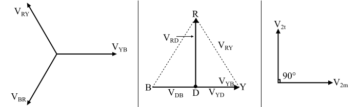
Phasor Diagram of Scott-T Connection
The phasor diagram of the Scott connection is shown in the figure.
Here, the line voltages of the three-phase balanced supply systb are −
$$\mathrm{V_{RY} \: = \: V_{YB} \: = \: V_{BR} \: = \: V_{L}}$$
Let VYB be taken as the reference phasor, then
$$\mathrm{V_{YB} \: = \: V_{L} \: \angle 0^{\circ}}$$
$$\mathrm{V_{RY} \: = \: V_{L} \: \angle + 120^{\circ}}$$
$$\mathrm{V_{BR} \: = \: V_{L} \: \angle - 120^{\circ}}$$
The figure also shows the voltages on the primary windings of the main and teaser transformers. Since, the centre tapping point D divides the primary winding YB of the main transformer into two equal halves. Therefore,
$$\mathrm{\text{Number of turns in portion } \: YD \: = \: \text{ Number of turns in portion } \: DB \: = \: \frac{N_{P}}{2}}$$
Hence, the voltages VYD and VDB are equal and in phase with the voltage VYB i.e.
$$\mathrm{V_{YD} \: = \: V_{DB} \: = \: \frac{VBC}{2} \: = \: \frac{V_{L}}{2} \: \angle 0^{\circ} \:\: \dotso \:(1)}$$
Now, the voltage between terminals R and D is
$$\mathrm{V_{RD} \: = \: V_{RY} \: + \: V_{YD} \: = \: V_{L} \: \angle 120^{\circ} \: + \: \frac{V_{L}}{2} \: \angle 0^{\circ}}$$
$$\mathrm{\Rightarrow \: V_{RD} \: = \: \left[V_{L}\left(-\frac{1}{2} \: + \: j\frac{\surd 3}{2}\right)\right] \: + \: \left[\frac{V_{L}}{2}(1 \: + \: j0)\right]}$$
$$\mathrm{\Rightarrow \: V_{RD} \: = \: j\frac{\surd 3}{2}V_{L} \: = \: 0.866 \: V_{L} \: \angle 90^{\circ} \:\: \dotso \: (2)}$$
Thus, the primary voltage VRD of the teaser transformer is 0.866 times of that of the main transformer and is 90° displaced from it in time.
The voltage VRD is applied to the primary winding of the teaser transformer. Thus, the secondary terminal voltage V2t of the teaser transformer will lead the secondary terminal voltage V2m of the main transformer. For the same flux in each transformer, the voltage per turn should be the same. To make the voltage per turn same in the primary windings of the main and teaser transformers, the number of turns in the primary of the teaser transformer should be
$$\mathrm{\text{Number of turns in winding RD, } \: N_{RD} \: = \: \frac{\surd 3}{2}N_{P}}$$
Then,
$$\mathrm{\frac{V_{2t}}{N_{S}} \: = \: \frac{V_{RD}}{N_{RD}}}$$
$$\mathrm{\Rightarrow \: V_{2t} \: = \: \frac{N_{S}}{N_{RD}}V_{RD} \: = \: \left(\frac{N_{S}}{\frac{\surd 3}{2}N_{P}}\right)\left(\frac{\surd 3}{2}V_{L}\right)}$$
$$\mathrm{\Rightarrow \: V_{2t} \: = \: \frac{N_{S}}{N_{P}}V_{L} \: = \: V_{2m} \:\: \dotso \: (3)}$$
Therefore, the secondary windings of both the main and teaser transformers have equal voltage in magnitude, but they are displaced by 90° in time so that they results in a balanced two-phase systb.
Relationship between Input and Output Currents
Let, IR, IY and IB are the line currents on the 3-phase input side.
I1m = Primary Current of Main Transformer
I2m = Secondary Current of Main Transformer
I1t = Primary Current of Teaser Transformer
I2t = Secondary Current of Teaser Transformer
Now, from the connection diagram,
$$\mathrm{I_{1t} \: = \: I_{R}}$$
As, the secondary windings of both the transformers are identical, thus,
$$\mathrm{|I_{2m}| \: = \: |I_{2t}| \: = \: I_{2}\:(say)}$$
If the magnetising current of the transformers is neglected, then the mmf balance equation of the teaser transformer is given by,
$$\mathrm{I_{1t}N_{RD} \: = \: I_{2t}N_{S}}$$
$$\mathrm{\Rightarrow \: I_{R}\left(\frac{\surd 3}{2}N_{p}\right)} \: = \: I_{2t}N_{S}$$
Therefore,
$$\mathrm{I_{R} \: = \: I_{1t} \: = \: \frac{2}{\surd 3}\left(\frac{N_{S}}{N_{P}}\right)I_{2t} \: = \: 1.15\:K\:I_{2t}\:\: \dotso \: (4)}$$
Where, K = $mathrm{(\frac{N_{S}}{N_{P}})}$ is the transformation ratio of the transformer. Hence,
$$\mathrm{I_{2t} \: = \: \frac{2}{\surd 3}\left(\frac{I_{R}}{K}\right)} \:\: \dotso \: (5)$$
Now, the MMF balance equation of the main transformer is,
$$\mathrm{I_{1m}N_{YD} \: - \: I_{1m}N_{BD} \: = \: I_{2m}N_{S}}$$
$$\mathrm{\Rightarrow \: I_{Y}\left(\frac{N_{P}}{2}\right) \: - \: I_{B}\left(\frac{N_{P}}{2}\right) \:= \: I_{2m}N_{S}}$$
$$\mathrm{\Rightarrow \: I_{Y} \: - \: I_{B} \: = \: 2\left(\frac{N_{S}}{N_{P}}\right)I_{2m}\:=\: 2\:K\:I_{2m}\:\:\dotso \: (6)}$$
Therefore,
$$\mathrm{I_{2m} \: = \: \frac{1}{2}\left({\frac{I_{Y} \: - \: I_{B}}{K}}\right)\:\: \dotso \: (7)}$$
Now, for a balanced 3-phase systb,
$$\mathrm{I_{R} \: + \: I_{Y} \: + \: I_{B} \: = \: 0}$$
$$\mathrm{\therefore \: I_{B} \: = \: - \: I_{R} \: - \: I_{Y} \:\: \dotso \: (8)}$$
Substituting the value of IB in the equation (6), we get,
$$\mathrm{I_{Y} \: - \: (-I_{R} \: - \: I_{Y}) \: = \: 2\:K\:I_{2m}}$$
$$\mathrm{\Rightarrow\: 2I_{Y} \: + \: I_{R} \: = \: 2\:K \:I_{2m}}$$
$$\mathrm{\Rightarrow\:I_{Y} \: = \: -\frac{I_{R}}{2} \: + \: K\: I_{2m} \:\: \dotso \: (9)}$$
Again, substituting the value of current IY in eq. (8), we have,
$$\mathrm{I_{B} \: = \: -I_{R} \: - \: \left(-\frac{I_{R}}{2} \: + \: K \:I_{2m}\right)}$$
$$\mathrm{\Rightarrow\:I_{B} \: = \: - \frac{I_{R}}{2} \: - \: K \:I_{2m} \:\: \dotso \: (10)}$$
These current equations are valid for balanced as well as unbalanced loads.
Applications of Scott-T Connection
The Scott connection of transformer is used in following applications −
- The Scott connection is used to link a 3-phase systb with a 2-phase systb with the flow of power in either direction.
- It is used to operate two 1-phase electric furnaces together when the power is drawn from the 3-phase supply.
- It is also used to supply 1-phase loads such as electric trains from the balanced three phase supply.