- Electrical Machines - Home
- Basic Concepts
- Electromechanical Energy Conversion
- Energy Stored in Magnetic Field
- Singly-Excited and Doubly Excited Systems
- Rotating Electrical Machines
- Electrical Machines Types
- Faraday’s Laws of Electromagnetic Induction
- Concept of Induced EMF
- Fleming's Left Hand and Right Hand Rules
- Transformers
- Electrical Transformer
- Construction of Transformer
- EMF Equation of Transformer
- Turns Ratio and Voltage Transformation Ratio
- Ideal Transformer
- Practical Transformer
- Ideal and Practical Transformers
- Transformer on DC
- Losses in a Transformer
- Efficiency of Transformer
- 3-Phase Transformer
- Types of Transformers
- More on Transformers
- Transformer Working Principle
- Single-Phase Transformer Working Principle
- 3-Phase Transformer Principle
- 3-Phase Induction Motor Torque-Slip
- 3-Phase Induction Motor Torque-Speed
- 3-Phase Transformer Harmonics
- Double-Star Connection (3-6 Phase)
- Double-delta Connection (3-6 Phase)
- Transformer Ratios
- Voltage Regulation
- Delta-Star Connection (3-Phase)
- Star-Delta Connection (3-Phase)
- Autotransformer Conversion
- Back-to-back Test (Sumpner's Test)
- Transformer Voltage Drop
- Autotransformer Output
- Open and Short Circuit Test
- 3-Phase Autotransformer
- Star-Star Connection
- 6-Phase Diametrical Connections
- Circuit Test (Three-Winding)
- Potential Transformer
- Transformers Parallel Operation
- Open Delta (V-V) Connection
- Autotransformer
- Current Transformer
- No-Load Current Wave
- Transformer Inrush Current
- Transformer Vector Groups
- 3 to 12-Phase Transformers
- Scott-T Transformer Connection
- Transformer kVA Rating
- Three-Winding Transformer
- Delta-Delta Connection Transformer
- Transformer DC Supply Issue
- Equivalent Circuit Transformer
- Simplified Equivalent Circuit of Transformer
- Transformer No-Load Condition
- Transformer Load Condition
- OTI WTI Transformer
- CVT Transformer
- Isolation vs Regular Transformer
- Dry vs Oil-Filled
- DC Machines
- Construction of DC Machines
- Types of DC Machines
- Working Principle of DC Generator
- EMF Equation of DC Generator
- Derivation of EMF Equation DC Generator
- Types of DC Generators
- Working Principle of DC Motor
- Back EMF in DC Motor
- Types of DC Motors
- Losses in DC Machines
- Applications of DC Machines
- More on DC Machines
- DC Generator
- DC Generator Armature Reaction
- DC Generator Commutator Action
- Stepper vs DC Motors
- DC Shunt Generators Critical Resistance
- DC Machines Commutation
- DC Motor Characteristics
- Synchronous Generator Working Principle
- DC Generator Characteristics
- DC Generator Demagnetizing & Cross-Magnetizing
- DC Motor Voltage & Power Equations
- DC Generator Efficiency
- Electric Breaking of DC Motors
- DC Motor Efficiency
- Four Quadrant Operation of DC Motors
- Open Circuit Characteristics of DC Generators
- Voltage Build-Up in Self-Excited DC Generators
- Types of Armature Winding in DC Machines
- Torque in DC Motors
- Swinburne’s Test of DC Machine
- Speed Control of DC Shunt Motor
- Speed Control of DC Series Motor
- DC Motor of Speed Regulation
- Hopkinson's Test
- Permanent Magnet DC Motor
- Permanent Magnet Stepper Motor
- DC Servo Motor Theory
- DC Series vs Shunt Motor
- BLDC Motor vs PMSM Motor
- Induction Motors
- Introduction to Induction Motor
- Single-Phase Induction Motor
- 3-Phase Induction Motor
- Construction of 3-Phase Induction Motor
- 3-Phase Induction Motor on Load
- Characteristics of 3-Phase Induction Motor
- Speed Regulation and Speed Control
- Methods of Starting 3-Phase Induction Motors
- More on Induction Motors
- 3-Phase Induction Motor Working Principle
- 3-Phase Induction Motor Rotor Parameters
- Double Cage Induction Motor Equivalent Circuit
- Induction Motor Equivalent Circuit Models
- Slip Ring vs Squirrel Cage Induction Motors
- Single-Cage vs Double-Cage Induction Motor
- Induction Motor Equivalent Circuits
- Induction Motor Crawling & Cogging
- Induction Motor Blocked Rotor Test
- Induction Motor Circle Diagram
- 3-Phase Induction Motors Applications
- 3-Phase Induction Motors Torque Ratios
- Induction Motors Power Flow Diagram & Losses
- Determining Induction Motor Efficiency
- Induction Motor Speed Control by Pole-Amplitude Modulation
- Induction Motor Inverted or Rotor Fed
- High Torque Cage Motors
- Double-Cage Induction Motor Torque-Slip Characteristics
- 3-Phase Induction Motors Starting Torque
- 3-phase Induction Motor - Rotor Resistance Starter
- 3-phase Induction Motor Running Torque
- 3-Phase Induction Motor - Rotating Magnetic Field
- Isolated Induction Generator
- Capacitor-Start Induction Motor
- Capacitor-Start Capacitor-Run Induction Motor
- Winding EMFs in 3-Phase Induction Motors
- Split-Phase Induction Motor
- Shaded Pole Induction Motor
- Repulsion-Start Induction-Run Motor
- Repulsion Induction Motor
- PSC Induction Motor
- Single-Phase Induction Motor Performance Analysis
- Linear Induction Motor
- Single-Phase Induction Motor Testing
- 3-Phase Induction Motor Fault Types
- Synchronous Machines
- Introduction to 3-Phase Synchronous Machines
- Construction of Synchronous Machine
- Working of 3-Phase Alternator
- Armature Reaction in Synchronous Machines
- Output Power of 3-Phase Alternator
- Losses and Efficiency of an Alternator
- Losses and Efficiency of 3-Phase Alternator
- Working of 3-Phase Synchronous Motor
- Equivalent Circuit and Power Factor of Synchronous Motor
- Power Developed by Synchronous Motor
- More on Synchronous Machines
- AC Motor Types
- Induction Generator (Asynchronous Generator)
- Synchronous Speed Slip of 3-Phase Induction Motor
- Armature Reaction in Alternator at Leading Power Factor
- Armature Reaction in Alternator at Lagging Power Factor
- Stationary Armature vs Rotating Field Alternator Advantages
- Synchronous Impedance Method for Voltage Regulation
- Saturated & Unsaturated Synchronous Reactance
- Synchronous Reactance & Impedance
- Significance of Short Circuit Ratio in Alternator
- Hunting Effect Alternator
- Hydrogen Cooling in Synchronous Generators
- Excitation System of Synchronous Machine
- Equivalent Circuit Phasor Diagram of Synchronous Generator
- EMF Equation of Synchronous Generator
- Cooling Methods for Synchronous Generators
- Assumptions in Synchronous Impedance Method
- Armature Reaction at Unity Power Factor
- Voltage Regulation of Alternator
- Synchronous Generator with Infinite Bus Operation
- Zero Power Factor of Synchronous Generator
- Short Circuit Ratio Calculation of Synchronous Machines
- Speed-Frequency Relationship in Alternator
- Pitch Factor in Alternator
- Max Reactive Power in Synchronous Generators
- Power Flow Equations for Synchronous Generator
- Potier Triangle for Voltage Regulation in Alternators
- Parallel Operation of Alternators
- Load Sharing in Parallel Alternators
- Slip Test on Synchronous Machine
- Constant Flux Linkage Theorem
- Blondel's Two Reaction Theory
- Synchronous Machine Oscillations
- Ampere Turn Method for Voltage Regulation
- Salient Pole Synchronous Machine Theory
- Synchronization by Synchroscope
- Synchronization by Synchronizing Lamp Method
- Sudden Short Circuit in 3-Phase Alternator
- Short Circuit Transient in Synchronous Machines
- Power-Angle of Salient Pole Machines
- Prime-Mover Governor Characteristics
- Power Input of Synchronous Generator
- Power Output of Synchronous Generator
- Power Developed by Salient Pole Motor
- Phasor Diagrams of Cylindrical Rotor Moto
- Synchronous Motor Excitation Voltage Determination
- Hunting Synchronous Motor
- Self-Starting Synchronous Motor
- Unidirectional Torque Production in Synchronous Motor
- Effect of Load Change on Synchronous Motor
- Field Excitation Effect on Synchronous Motor
- Output Power of Synchronous Motor
- Input Power of Synchronous Motor
- V Curves & Inverted V Curves of Synchronous Motor
- Torque in Synchronous Motor
- Construction of 3-Phase Synchronous Motor
- Synchronous Motor
- Synchronous Condenser
- Power Flow in Synchronous Motor
- Types of Faults in Alternator
- Miscellaneous Topics
- Electrical Generator
- Determining Electric Motor Load
- Solid State Motor Starters
- Characteristics of Single-Phase Motor
- Types of AC Generators
- Three-Point Starter
- Four-Point Starter
- Ward Leonard Speed Control Method
- Pole Changing Method
- Stator Voltage Control Method
- DOL Starter
- Star-Delta Starter
- Hysteresis Motor
- 2-Phase & 3-Phase AC Servo Motors
- Repulsion Motor
- Reluctance Motor
- Stepper Motor
- PCB Motor
- Single-Stack Variable Reluctance Stepper Motor
- Schrage Motor
- Hybrid Schrage Motor
- Multi-Stack Variable Reluctance Stepper Motor
- Universal Motor
- Step Angle in Stepper Motor
- Stepper Motor Torque-Pulse Rate Characteristics
- Distribution Factor
- Electrical Machines Basic Terms
- Synchronizing Torque Coefficient
- Synchronizing Power Coefficient
- Metadyne
- Motor Soft Starter
- CVT vs PT
- Metering CT vs Protection CT
- Stator and Rotor in Electrical Machines
- Electric Motor Winding
- Electric Motor
- Useful Resources
- Quick Guide
- Resources
- Discussion
Difference between CVT and PT
In electrical engineering, there are several different types of transformers for different applications. Two such transformers are CVT and PT. CVT stands for Capacitive Voltage Transformer and PT stands for Potential Transformer.
Both CVT and PT are the types of instrument transformers and thus are used in protection and metering applications. However, they are different from each other in many aspects. The primary difference between CVT and PT is that a CVT (Capacitive Voltage Transformer) utilizes a capacitor voltage divider and a step-down transformer to convert a high voltage into a low voltage, while a PT (Potential Transformer) utilizes only a step-down transformer to reduce the voltage level.
There are numerous other differences between CVT and PT which we will discuss in this article. But before that lets have an overview of CVT and PT individually.
What is a CVT?
A CVT (Capacitive Voltage Transformer) is a device used in electrical systems to reduce the high voltages of power lines into low voltages suitable for measurement and protection.
A CVT is a specially designed step-down transformer in which a capacitor voltage divider is employed along with a step-down transformer for reduction of the voltage level.
The circuit diagram of a typical capacitive voltage transformer or CVT is depicted in the following figure
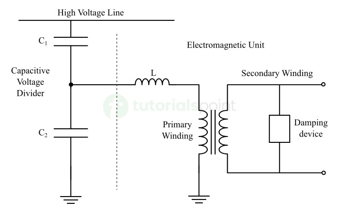
We can see that it consists of the following two major components
Capacitor Voltage Divider This circuit consists of two series connected capacitors. This capacitor voltage divider is connected across the transmission line whose voltage is to be reduced. This voltage divider reduces the voltage of the power line significantly by using the principle of voltage division between capacitors. This reduced voltage is then applied to the electromagnetic unit of the CVT.
Step - Down Transformer It is another essential component of a CVT which is tagged as the electromagnetic unit in the CVT. The function this transformer is to further reduce the voltage from the capacitor voltage divider to a value that can be safely applied to a protecting or metering device.
Applications of CVT
It is clear that a CVT consists of a voltage transformer and a capacitor element. For this reason, it is referred to as a capacitive voltage transformer.
CVTs are used in electrical power systems for the following purposes: Measurement of high-voltages of transmission lines, Protection purposes, For monitoring insulation levels in system, Filtering harmonics from the system, etc.
What is a PT?
PT (Potential Transformer) is another type of voltage step-down transformer used in power systems for reducing the high voltages of transmission lines to a low value suitable for metering and protection purposes.
Sometimes, a PT is also referred to as a voltage transformer or VT. Like CVT, PT is also an instrument transformer because it is employed for metering and protection of the system.
The circuit diagram of a PT or potential transformer is depicted in the following figure
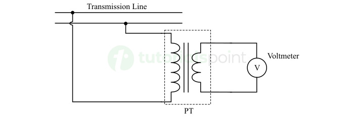
It can be seen that a PT consists of three main components namely,
Primary Winding A coil to which high input voltage is applied for stepping it down.
Secondary Winding A coil from which reduced voltage is taken as output.
Magnetic Core To carry the magnetic flux from primary winding to the secondary winding for mutual induction.
It is clear that the construction of a PT or potential transformer is similar to an ordinary voltage step-down transformer used in power system. Also, the working principle of a PT is based on electromagnetic induction only.
Applications of Potential Transformer
PTs are also used in metering, protection, and control applications in electrical power systems. Some of the key applications of PTs are as follows
- Measurement of voltage in transmission and distribution lines,
- Protection of power system and operate the protective relays,
- Monitoring the power system for voltage fluctuations to reduce power quality problems,
- To provide control signals to control and communication devices, etc.
After getting a brief overview of CVT and PT, let us now highlight the important differences between them.
Difference between CVT and PT
The following table highlights all the significant differences between CVT (Capacitive Voltage Transformer) and PT (Potential Transformer)
| Parameter | CVT | PT |
|---|---|---|
| Full form | CVT stands for Capacitive Voltage Transformer or Capacitor Voltage Transformer. | PT stands for Potential Transformer. |
| Components | CVT has a capacitor voltage divider and a step-down transformer to reduce the high voltages. | PT has a step-down transformer only for reducing the high voltages. |
| Working principle | The working of a CVT is based on the principle of voltage division and electromagnetic induction. | The working of a PT is based on the principle of electromagnetic induction. |
| Voltage step-down process | A CVT first reduces the voltage using a capacitor voltage divider and then this reduced voltage is further stepped down using a step-down transformer. | A PT reduces the voltage using a step-down transformer only. |
| Voltage rating | CVTs are rated for extra high voltage levels, typically greater than 220 kV. | PTs are generally rated for low, medium, and high voltage levels up to 220 kV. |
| Core losses | Due to small sized magnetic core, CVTs has low iron or core losses. | PTs have a large magnetic core and thus these have very high core or iron losses. |
| Frequency response | CVTs have a wider frequency response. | The frequency response of PTs is narrower. |
| Coupling of PLCC | CVTs can be used for coupling of PLCC (Power Line Carrier Communication) due to their high frequency response. | PTs are not suitable for PLCC coupling. |
| Weight | CVT are lighter in weight due to their small core size. | PTs are relatively heavier than CVTs. |
| Cost | CVTs are less expensive for extra-high voltage applications. | PTs are relatively expensive than CVTs for extra high voltage applications. |
| Design complexity | CVTs have a relatively complex design due to the presence of additional capacitor voltage divider. | PTs have a simple design as they use only an electromagnetic unit. |
| Reliability | CVTs are more reliable at extra-high voltages. | PTs are not much reliable as the CVTs. This is due to the problems associated with their magnetic core and windings. |
| Insulation level | CVTs have a very high insulation level, thus they can be used in extra high voltage applications. | PTs do not have insulation level as high in CVTs. Thus, they are generally used in medium and high voltage applications only. |
| Effect of frequency variations | CVTs use capacitor component. Hence, their performance is affected by the variations in frequency. | The performance of PTs is less affected by the variations in frequency. |
| Applications | CVTs are mainly used in extra-high voltage power systems for voltage measurement, protection, and power line carrier communication. | PTs are used in low to high voltage power systems for protection and voltage measurement. |
Conclusion
From the above discussion, we can conclude that the primary function of a CVT and a PT is that same, i.e., reducing high-voltage to a lower value for measurement and protection purposes. But they are completely different from each other in construction, working principle, applications, and many other aspects.