- Electrical Machines - Home
- Basic Concepts
- Electromechanical Energy Conversion
- Energy Stored in Magnetic Field
- Singly-Excited and Doubly Excited Systems
- Rotating Electrical Machines
- Electrical Machines Types
- Faraday’s Laws of Electromagnetic Induction
- Concept of Induced EMF
- Fleming's Left Hand and Right Hand Rules
- Transformers
- Electrical Transformer
- Construction of Transformer
- EMF Equation of Transformer
- Turns Ratio and Voltage Transformation Ratio
- Ideal Transformer
- Practical Transformer
- Ideal and Practical Transformers
- Transformer on DC
- Losses in a Transformer
- Efficiency of Transformer
- 3-Phase Transformer
- Types of Transformers
- More on Transformers
- Transformer Working Principle
- Single-Phase Transformer Working Principle
- 3-Phase Transformer Principle
- 3-Phase Induction Motor Torque-Slip
- 3-Phase Induction Motor Torque-Speed
- 3-Phase Transformer Harmonics
- Double-Star Connection (3-6 Phase)
- Double-delta Connection (3-6 Phase)
- Transformer Ratios
- Voltage Regulation
- Delta-Star Connection (3-Phase)
- Star-Delta Connection (3-Phase)
- Autotransformer Conversion
- Back-to-back Test (Sumpner's Test)
- Transformer Voltage Drop
- Autotransformer Output
- Open and Short Circuit Test
- 3-Phase Autotransformer
- Star-Star Connection
- 6-Phase Diametrical Connections
- Circuit Test (Three-Winding)
- Potential Transformer
- Transformers Parallel Operation
- Open Delta (V-V) Connection
- Autotransformer
- Current Transformer
- No-Load Current Wave
- Transformer Inrush Current
- Transformer Vector Groups
- 3 to 12-Phase Transformers
- Scott-T Transformer Connection
- Transformer kVA Rating
- Three-Winding Transformer
- Delta-Delta Connection Transformer
- Transformer DC Supply Issue
- Equivalent Circuit Transformer
- Simplified Equivalent Circuit of Transformer
- Transformer No-Load Condition
- Transformer Load Condition
- OTI WTI Transformer
- CVT Transformer
- Isolation vs Regular Transformer
- Dry vs Oil-Filled
- DC Machines
- Construction of DC Machines
- Types of DC Machines
- Working Principle of DC Generator
- EMF Equation of DC Generator
- Derivation of EMF Equation DC Generator
- Types of DC Generators
- Working Principle of DC Motor
- Back EMF in DC Motor
- Types of DC Motors
- Losses in DC Machines
- Applications of DC Machines
- More on DC Machines
- DC Generator
- DC Generator Armature Reaction
- DC Generator Commutator Action
- Stepper vs DC Motors
- DC Shunt Generators Critical Resistance
- DC Machines Commutation
- DC Motor Characteristics
- Synchronous Generator Working Principle
- DC Generator Characteristics
- DC Generator Demagnetizing & Cross-Magnetizing
- DC Motor Voltage & Power Equations
- DC Generator Efficiency
- Electric Breaking of DC Motors
- DC Motor Efficiency
- Four Quadrant Operation of DC Motors
- Open Circuit Characteristics of DC Generators
- Voltage Build-Up in Self-Excited DC Generators
- Types of Armature Winding in DC Machines
- Torque in DC Motors
- Swinburne’s Test of DC Machine
- Speed Control of DC Shunt Motor
- Speed Control of DC Series Motor
- DC Motor of Speed Regulation
- Hopkinson's Test
- Permanent Magnet DC Motor
- Permanent Magnet Stepper Motor
- DC Servo Motor Theory
- DC Series vs Shunt Motor
- BLDC Motor vs PMSM Motor
- Induction Motors
- Introduction to Induction Motor
- Single-Phase Induction Motor
- 3-Phase Induction Motor
- Construction of 3-Phase Induction Motor
- 3-Phase Induction Motor on Load
- Characteristics of 3-Phase Induction Motor
- Speed Regulation and Speed Control
- Methods of Starting 3-Phase Induction Motors
- More on Induction Motors
- 3-Phase Induction Motor Working Principle
- 3-Phase Induction Motor Rotor Parameters
- Double Cage Induction Motor Equivalent Circuit
- Induction Motor Equivalent Circuit Models
- Slip Ring vs Squirrel Cage Induction Motors
- Single-Cage vs Double-Cage Induction Motor
- Induction Motor Equivalent Circuits
- Induction Motor Crawling & Cogging
- Induction Motor Blocked Rotor Test
- Induction Motor Circle Diagram
- 3-Phase Induction Motors Applications
- 3-Phase Induction Motors Torque Ratios
- Induction Motors Power Flow Diagram & Losses
- Determining Induction Motor Efficiency
- Induction Motor Speed Control by Pole-Amplitude Modulation
- Induction Motor Inverted or Rotor Fed
- High Torque Cage Motors
- Double-Cage Induction Motor Torque-Slip Characteristics
- 3-Phase Induction Motors Starting Torque
- 3-phase Induction Motor - Rotor Resistance Starter
- 3-phase Induction Motor Running Torque
- 3-Phase Induction Motor - Rotating Magnetic Field
- Isolated Induction Generator
- Capacitor-Start Induction Motor
- Capacitor-Start Capacitor-Run Induction Motor
- Winding EMFs in 3-Phase Induction Motors
- Split-Phase Induction Motor
- Shaded Pole Induction Motor
- Repulsion-Start Induction-Run Motor
- Repulsion Induction Motor
- PSC Induction Motor
- Single-Phase Induction Motor Performance Analysis
- Linear Induction Motor
- Single-Phase Induction Motor Testing
- 3-Phase Induction Motor Fault Types
- Synchronous Machines
- Introduction to 3-Phase Synchronous Machines
- Construction of Synchronous Machine
- Working of 3-Phase Alternator
- Armature Reaction in Synchronous Machines
- Output Power of 3-Phase Alternator
- Losses and Efficiency of an Alternator
- Losses and Efficiency of 3-Phase Alternator
- Working of 3-Phase Synchronous Motor
- Equivalent Circuit and Power Factor of Synchronous Motor
- Power Developed by Synchronous Motor
- More on Synchronous Machines
- AC Motor Types
- Induction Generator (Asynchronous Generator)
- Synchronous Speed Slip of 3-Phase Induction Motor
- Armature Reaction in Alternator at Leading Power Factor
- Armature Reaction in Alternator at Lagging Power Factor
- Stationary Armature vs Rotating Field Alternator Advantages
- Synchronous Impedance Method for Voltage Regulation
- Saturated & Unsaturated Synchronous Reactance
- Synchronous Reactance & Impedance
- Significance of Short Circuit Ratio in Alternator
- Hunting Effect Alternator
- Hydrogen Cooling in Synchronous Generators
- Excitation System of Synchronous Machine
- Equivalent Circuit Phasor Diagram of Synchronous Generator
- EMF Equation of Synchronous Generator
- Cooling Methods for Synchronous Generators
- Assumptions in Synchronous Impedance Method
- Armature Reaction at Unity Power Factor
- Voltage Regulation of Alternator
- Synchronous Generator with Infinite Bus Operation
- Zero Power Factor of Synchronous Generator
- Short Circuit Ratio Calculation of Synchronous Machines
- Speed-Frequency Relationship in Alternator
- Pitch Factor in Alternator
- Max Reactive Power in Synchronous Generators
- Power Flow Equations for Synchronous Generator
- Potier Triangle for Voltage Regulation in Alternators
- Parallel Operation of Alternators
- Load Sharing in Parallel Alternators
- Slip Test on Synchronous Machine
- Constant Flux Linkage Theorem
- Blondel's Two Reaction Theory
- Synchronous Machine Oscillations
- Ampere Turn Method for Voltage Regulation
- Salient Pole Synchronous Machine Theory
- Synchronization by Synchroscope
- Synchronization by Synchronizing Lamp Method
- Sudden Short Circuit in 3-Phase Alternator
- Short Circuit Transient in Synchronous Machines
- Power-Angle of Salient Pole Machines
- Prime-Mover Governor Characteristics
- Power Input of Synchronous Generator
- Power Output of Synchronous Generator
- Power Developed by Salient Pole Motor
- Phasor Diagrams of Cylindrical Rotor Moto
- Synchronous Motor Excitation Voltage Determination
- Hunting Synchronous Motor
- Self-Starting Synchronous Motor
- Unidirectional Torque Production in Synchronous Motor
- Effect of Load Change on Synchronous Motor
- Field Excitation Effect on Synchronous Motor
- Output Power of Synchronous Motor
- Input Power of Synchronous Motor
- V Curves & Inverted V Curves of Synchronous Motor
- Torque in Synchronous Motor
- Construction of 3-Phase Synchronous Motor
- Synchronous Motor
- Synchronous Condenser
- Power Flow in Synchronous Motor
- Types of Faults in Alternator
- Miscellaneous Topics
- Electrical Generator
- Determining Electric Motor Load
- Solid State Motor Starters
- Characteristics of Single-Phase Motor
- Types of AC Generators
- Three-Point Starter
- Four-Point Starter
- Ward Leonard Speed Control Method
- Pole Changing Method
- Stator Voltage Control Method
- DOL Starter
- Star-Delta Starter
- Hysteresis Motor
- 2-Phase & 3-Phase AC Servo Motors
- Repulsion Motor
- Reluctance Motor
- Stepper Motor
- PCB Motor
- Single-Stack Variable Reluctance Stepper Motor
- Schrage Motor
- Hybrid Schrage Motor
- Multi-Stack Variable Reluctance Stepper Motor
- Universal Motor
- Step Angle in Stepper Motor
- Stepper Motor Torque-Pulse Rate Characteristics
- Distribution Factor
- Electrical Machines Basic Terms
- Synchronizing Torque Coefficient
- Synchronizing Power Coefficient
- Metadyne
- Motor Soft Starter
- CVT vs PT
- Metering CT vs Protection CT
- Stator and Rotor in Electrical Machines
- Electric Motor Winding
- Electric Motor
- Useful Resources
- Quick Guide
- Resources
- Discussion
Difference Between DC Series Motor and Shunt Motor
A dc motor is a most basic type of electric motor that works on direct current supply. A typical dc motor consists of two main parts namely, magnetic field system and an armature. DC Machines are used in various applications such as toys, computers, printers, industrial machinery, and more. Based on the construction, the dc motors can be classified in three types namely, dc series motor, dc shunt motor, and dc compound motor.
In this article, I will explain what are the dc series and shunt motors and what are the key differences between them. So, lets get started with the basics of DC series and shunt motors.
What is a DC Series Motor?
A dc series motor is one in which the armature winding and the field winding are connected in series as shown in the following figure.
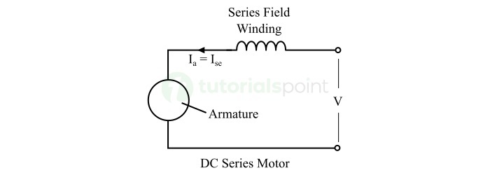
Since the field winding and armature winding are connected in series, therefore, the current flowing in the field winding is equal to the armature current. This armature current when passes through the series field winding, it produces a working magnetic field in the machine.
DC Series motors are known for their extremely high starting torque. Hence, they are mainly used in applications where very high starting torque is required such as in cranes, hoists, locomotives, lifts, etc.
What is a DC Shunt Motor?
A dc shunt motor is a type of dc motor which has field winding connected in parallel to the armature winding as shown in the following figure.
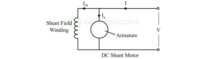
Since the armature winding and field winding in a dc shunt motor are connected in parallel, hence, the field winding receives the same supply voltage as the armature winding. Also, the voltage across and current through the shunt field winding remains the same. Thus, the dc shunt motor operates at a constant speed.
DC shunt motors also provide a simple speed control mechanism by varying the field current by changing the field winding resistance. However, the starting torque of dc shunt motor is lower than that of the dc series motor. For this reason, they are used in applications where medium starting torque and constant speed is desired like in elevators, printers, toys, etc.
After getting a brief overview of DC series motor and DC shunt motor, let us now discuss the key differences between them.
Difference between DC Series Motor and DC Shunt Motor
The following table highlights all the significant differences between dc series motor and dc shunt motor
| Parameter | DC Series Motor | Shunt Motor |
|---|---|---|
| Basic | In a dc series motor, the field winding is connected in series with the armature winding. | In a dc shunt motor, the field winding is connected in parallel with the armature winding. |
| Field current | In dc series motors, the field current is same as the armature current. | In dc shunt motors, the field current is not equal to armature current. |
| Voltage across armature and field windings | In dc series motors, the voltages across armature and field windings are different depending on their resistance. | In dc shunt motors, the voltage across the armature winding and field winding is same and is equal to the supply voltage. |
| Field winding design | A dc series motor has a field winding design with few turns of thick conductor wire. | The field winding of a dc shunt motor is designed with large number of turns of fine wire. |
| Resistance of field winding | The field winding of a dc series motor has very low resistance as it carries full armature current. | The field winding of a dc shunt motor has a very high resistance, so that it draws a very small current. |
| Staring torque | A dc series motor develops very high starting torque. | A dc shunt motor develops low and constant starting torque. |
| Torque-current relation | In dc series motors, the torque is directly proportional to the square of the armature current i.e., | In dc shunt motors, the torque is directly proportional to the armature current i.e., |
| Starting current | High starting current due to combined field and armature winding in series. | Lower starting current due to the parallel winding arrangement. |
| Speed | The dc series motors are variable speed dc motors. | The dc shunt motors are approximately constant speed motors. |
| Starter | To start dc series motors, the four-point starter is used. | To start dc shunt motors, three-point starter is used. |
| Speed-load characteristics | DC series motors have low speed at high loads, whereas dangerously high speed at low loads. | There is not significant change in the speed of dc shunt motor with the change in load. |
| Speed regulation | Poor speed regulation | Its speed regulation is better as compared to the DC Series motor. |
| Dynamic response | DC series motors have a faster dynamic response due to high starting torque. | The dynamic response of dc shunt motors is lower as compared to dc series motors. |
| Rotor design | The design of rotor of dc series motors is optimized for high starting torque. | In dc shunt motors, the rotor design is optimized for constant speeds. |
| Energy efficiency | DC series motors have lower energy efficiency at high speeds and light loads. | DC shunt motors provide better energy efficiency at a wide range of speeds and loads. |
| Field current adjustment | In dc series motors, it is not possible to adjust the field current independently as it has same field and armature currents. | In dc shunt motors, the field current can be adjusted independently without affecting the armature current. |
| Need of load balancing mechanism | DC series motors require a load balancing mechanism to prevent over speeding. | There is no need of this kind of mechanism as they have almost constant speed. |
| Applications | DC series motors are used for applications where high starting torque is required like in electric locomotives, hoists & cranes, electric bikes and cars, etc. | DC shunt motors are used in applications where constant speed is required like in fans, blowers, elevators, centrifugal pumps, lath machines, etc. |
Conclusion
A DC motor is an electric machine that converts direct current electricity into mechanical energy. DC motors can be of three major types namely, dc series motors, dc shunt motors, and dc compound motors. The dc series and shunt motors are widely used in variety of applications and they are completely different in terms of their construction and operating characteristics.
DC series motors have a field winding connected in series with the armature winding and known for their high starting toque. On the other hand, dc shunt motors have a field winding connected in parallel with the armature winding and known for their constant speed and good speed regulation properties. In this comprehensive article, I have explained the basic theory of dc series and shunt motors along with the key differences between them.