- Electrical Machines - Home
- Basic Concepts
- Electromechanical Energy Conversion
- Energy Stored in Magnetic Field
- Singly-Excited and Doubly Excited Systems
- Rotating Electrical Machines
- Electrical Machines Types
- Faraday’s Laws of Electromagnetic Induction
- Concept of Induced EMF
- Fleming's Left Hand and Right Hand Rules
- Transformers
- Electrical Transformer
- Construction of Transformer
- EMF Equation of Transformer
- Turns Ratio and Voltage Transformation Ratio
- Ideal Transformer
- Practical Transformer
- Ideal and Practical Transformers
- Transformer on DC
- Losses in a Transformer
- Efficiency of Transformer
- 3-Phase Transformer
- Types of Transformers
- More on Transformers
- Transformer Working Principle
- Single-Phase Transformer Working Principle
- 3-Phase Transformer Principle
- 3-Phase Induction Motor Torque-Slip
- 3-Phase Induction Motor Torque-Speed
- 3-Phase Transformer Harmonics
- Double-Star Connection (3-6 Phase)
- Double-delta Connection (3-6 Phase)
- Transformer Ratios
- Voltage Regulation
- Delta-Star Connection (3-Phase)
- Star-Delta Connection (3-Phase)
- Autotransformer Conversion
- Back-to-back Test (Sumpner's Test)
- Transformer Voltage Drop
- Autotransformer Output
- Open and Short Circuit Test
- 3-Phase Autotransformer
- Star-Star Connection
- 6-Phase Diametrical Connections
- Circuit Test (Three-Winding)
- Potential Transformer
- Transformers Parallel Operation
- Open Delta (V-V) Connection
- Autotransformer
- Current Transformer
- No-Load Current Wave
- Transformer Inrush Current
- Transformer Vector Groups
- 3 to 12-Phase Transformers
- Scott-T Transformer Connection
- Transformer kVA Rating
- Three-Winding Transformer
- Delta-Delta Connection Transformer
- Transformer DC Supply Issue
- Equivalent Circuit Transformer
- Simplified Equivalent Circuit of Transformer
- Transformer No-Load Condition
- Transformer Load Condition
- OTI WTI Transformer
- CVT Transformer
- Isolation vs Regular Transformer
- Dry vs Oil-Filled
- DC Machines
- Construction of DC Machines
- Types of DC Machines
- Working Principle of DC Generator
- EMF Equation of DC Generator
- Derivation of EMF Equation DC Generator
- Types of DC Generators
- Working Principle of DC Motor
- Back EMF in DC Motor
- Types of DC Motors
- Losses in DC Machines
- Applications of DC Machines
- More on DC Machines
- DC Generator
- DC Generator Armature Reaction
- DC Generator Commutator Action
- Stepper vs DC Motors
- DC Shunt Generators Critical Resistance
- DC Machines Commutation
- DC Motor Characteristics
- Synchronous Generator Working Principle
- DC Generator Characteristics
- DC Generator Demagnetizing & Cross-Magnetizing
- DC Motor Voltage & Power Equations
- DC Generator Efficiency
- Electric Breaking of DC Motors
- DC Motor Efficiency
- Four Quadrant Operation of DC Motors
- Open Circuit Characteristics of DC Generators
- Voltage Build-Up in Self-Excited DC Generators
- Types of Armature Winding in DC Machines
- Torque in DC Motors
- Swinburne’s Test of DC Machine
- Speed Control of DC Shunt Motor
- Speed Control of DC Series Motor
- DC Motor of Speed Regulation
- Hopkinson's Test
- Permanent Magnet DC Motor
- Permanent Magnet Stepper Motor
- DC Servo Motor Theory
- DC Series vs Shunt Motor
- BLDC Motor vs PMSM Motor
- Induction Motors
- Introduction to Induction Motor
- Single-Phase Induction Motor
- 3-Phase Induction Motor
- Construction of 3-Phase Induction Motor
- 3-Phase Induction Motor on Load
- Characteristics of 3-Phase Induction Motor
- Speed Regulation and Speed Control
- Methods of Starting 3-Phase Induction Motors
- More on Induction Motors
- 3-Phase Induction Motor Working Principle
- 3-Phase Induction Motor Rotor Parameters
- Double Cage Induction Motor Equivalent Circuit
- Induction Motor Equivalent Circuit Models
- Slip Ring vs Squirrel Cage Induction Motors
- Single-Cage vs Double-Cage Induction Motor
- Induction Motor Equivalent Circuits
- Induction Motor Crawling & Cogging
- Induction Motor Blocked Rotor Test
- Induction Motor Circle Diagram
- 3-Phase Induction Motors Applications
- 3-Phase Induction Motors Torque Ratios
- Induction Motors Power Flow Diagram & Losses
- Determining Induction Motor Efficiency
- Induction Motor Speed Control by Pole-Amplitude Modulation
- Induction Motor Inverted or Rotor Fed
- High Torque Cage Motors
- Double-Cage Induction Motor Torque-Slip Characteristics
- 3-Phase Induction Motors Starting Torque
- 3-phase Induction Motor - Rotor Resistance Starter
- 3-phase Induction Motor Running Torque
- 3-Phase Induction Motor - Rotating Magnetic Field
- Isolated Induction Generator
- Capacitor-Start Induction Motor
- Capacitor-Start Capacitor-Run Induction Motor
- Winding EMFs in 3-Phase Induction Motors
- Split-Phase Induction Motor
- Shaded Pole Induction Motor
- Repulsion-Start Induction-Run Motor
- Repulsion Induction Motor
- PSC Induction Motor
- Single-Phase Induction Motor Performance Analysis
- Linear Induction Motor
- Single-Phase Induction Motor Testing
- 3-Phase Induction Motor Fault Types
- Synchronous Machines
- Introduction to 3-Phase Synchronous Machines
- Construction of Synchronous Machine
- Working of 3-Phase Alternator
- Armature Reaction in Synchronous Machines
- Output Power of 3-Phase Alternator
- Losses and Efficiency of an Alternator
- Losses and Efficiency of 3-Phase Alternator
- Working of 3-Phase Synchronous Motor
- Equivalent Circuit and Power Factor of Synchronous Motor
- Power Developed by Synchronous Motor
- More on Synchronous Machines
- AC Motor Types
- Induction Generator (Asynchronous Generator)
- Synchronous Speed Slip of 3-Phase Induction Motor
- Armature Reaction in Alternator at Leading Power Factor
- Armature Reaction in Alternator at Lagging Power Factor
- Stationary Armature vs Rotating Field Alternator Advantages
- Synchronous Impedance Method for Voltage Regulation
- Saturated & Unsaturated Synchronous Reactance
- Synchronous Reactance & Impedance
- Significance of Short Circuit Ratio in Alternator
- Hunting Effect Alternator
- Hydrogen Cooling in Synchronous Generators
- Excitation System of Synchronous Machine
- Equivalent Circuit Phasor Diagram of Synchronous Generator
- EMF Equation of Synchronous Generator
- Cooling Methods for Synchronous Generators
- Assumptions in Synchronous Impedance Method
- Armature Reaction at Unity Power Factor
- Voltage Regulation of Alternator
- Synchronous Generator with Infinite Bus Operation
- Zero Power Factor of Synchronous Generator
- Short Circuit Ratio Calculation of Synchronous Machines
- Speed-Frequency Relationship in Alternator
- Pitch Factor in Alternator
- Max Reactive Power in Synchronous Generators
- Power Flow Equations for Synchronous Generator
- Potier Triangle for Voltage Regulation in Alternators
- Parallel Operation of Alternators
- Load Sharing in Parallel Alternators
- Slip Test on Synchronous Machine
- Constant Flux Linkage Theorem
- Blondel's Two Reaction Theory
- Synchronous Machine Oscillations
- Ampere Turn Method for Voltage Regulation
- Salient Pole Synchronous Machine Theory
- Synchronization by Synchroscope
- Synchronization by Synchronizing Lamp Method
- Sudden Short Circuit in 3-Phase Alternator
- Short Circuit Transient in Synchronous Machines
- Power-Angle of Salient Pole Machines
- Prime-Mover Governor Characteristics
- Power Input of Synchronous Generator
- Power Output of Synchronous Generator
- Power Developed by Salient Pole Motor
- Phasor Diagrams of Cylindrical Rotor Moto
- Synchronous Motor Excitation Voltage Determination
- Hunting Synchronous Motor
- Self-Starting Synchronous Motor
- Unidirectional Torque Production in Synchronous Motor
- Effect of Load Change on Synchronous Motor
- Field Excitation Effect on Synchronous Motor
- Output Power of Synchronous Motor
- Input Power of Synchronous Motor
- V Curves & Inverted V Curves of Synchronous Motor
- Torque in Synchronous Motor
- Construction of 3-Phase Synchronous Motor
- Synchronous Motor
- Synchronous Condenser
- Power Flow in Synchronous Motor
- Types of Faults in Alternator
- Miscellaneous Topics
- Electrical Generator
- Determining Electric Motor Load
- Solid State Motor Starters
- Characteristics of Single-Phase Motor
- Types of AC Generators
- Three-Point Starter
- Four-Point Starter
- Ward Leonard Speed Control Method
- Pole Changing Method
- Stator Voltage Control Method
- DOL Starter
- Star-Delta Starter
- Hysteresis Motor
- 2-Phase & 3-Phase AC Servo Motors
- Repulsion Motor
- Reluctance Motor
- Stepper Motor
- PCB Motor
- Single-Stack Variable Reluctance Stepper Motor
- Schrage Motor
- Hybrid Schrage Motor
- Multi-Stack Variable Reluctance Stepper Motor
- Universal Motor
- Step Angle in Stepper Motor
- Stepper Motor Torque-Pulse Rate Characteristics
- Distribution Factor
- Electrical Machines Basic Terms
- Synchronizing Torque Coefficient
- Synchronizing Power Coefficient
- Metadyne
- Motor Soft Starter
- CVT vs PT
- Metering CT vs Protection CT
- Stator and Rotor in Electrical Machines
- Electric Motor Winding
- Electric Motor
- Useful Resources
- Quick Guide
- Resources
- Discussion
Transformers Open Delta (V-V) Connection
If one transformer of delta-delta connected transformer bank is damaged or opened, then rest of the system will continue to supply the 3-phase power. If this damaged transformer is isolated, the remaining two transformers will function as a 3-phase bank with rating reduced to about 58 % that of the original delta-delta bank. This type of arrangement is known as open-delta or V-V connection.
Therefore, in the case of open-delta or V-V connection, two instead of three 1-phase transformers are used for three-phase operation.
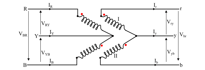
Now, let VRY, VYB and VBR be the applied voltages to the primary winding. The voltage induced in the secondary winding-I is Vry and the voltage induced in the secondary winding-II is Vyb. As, there is no winding between the points r and b, but there is a voltage between the points r and b. This voltage can be determined by applying KVL in the closed loop on the secondary side. Hence,
$$\mathrm{V_{ry} \: + \: V_{yb} \: + \: V_{br} \: = \: 0}$$
$$\mathrm{\Rightarrow \: V_{br} \: = \: - \: V_{ry} \: - \: V_{yb} \:\: \dotso \: (1)}$$
If VLP is the magnitude of line voltage on the primary side, then,
$$\mathrm{V_{RY} \: = \: V_{LP} \: \angle 0^{\circ}}$$
$$\mathrm{V_{YB} \: = \: V_{LP} \: \angle - 120^{\circ}}$$
$$\mathrm{V_{BR} \: = \: V_{LP} \: \angle + 120^{\circ}}$$
If the leakage impedances of the transformers are neglected, then,
$$\mathrm{V_{ry} \: = \: V_{LS} \: \angle 0^{\circ}}$$
$$\mathrm{V_{yb} \: = \: V_{LS} \: \angle - 120^{\circ}}$$
Where, VLS is the magnitude of the line voltage on the secondary side.
Now, by substituting the values of Vry and Vyb in the equation (1), we get,
$$\mathrm{V_{br} \: = \: - \: V_{LS} \: \angle 0^{\circ} \: - \: V_{LS} \: \angle - 120^{\circ}}$$
$$\mathrm{\Rightarrow \: V_{br} \: = \: (-V_{LS} \: - \: j0) \: - \: (-0.5V_{LS} \: - \: j0.866V_{LS})}$$
$$\mathrm{\Rightarrow \: V_{br} \: = \: - 0.5V_{LS} \: + \: j0.866V_{LS} \: = \: V_{LS} \: \angle + 120^{\circ} \: \dotso \: (2)}$$
From the eqn. (2), it can be seen that the voltage Vbr is equal in magnitude to the secondary line voltage and 120° displaced in time from the other two secondary voltages. Therefore, if the balanced 3-phase supply is connected to the primary windings of the open-delta connection, the balanced three-phase voltages are produced on the secondary sides, when the leakage impedances are negligible.
Open-Delta Connection Calculations and Formulae
If V_{2} and I_{2} are the rated secondary voltage and rated secondary current respectively of the delta-delta connected transformer. Then, the line current to the load of a delta connected system is √3I_{2}. Therefore, the normal delta load VA is,
$$\mathrm{S_{\triangle \: - \: \triangle} \: = \: \surd 3 \: \times \: \text{ line voltage } \: \times \: \text{ line current}}$$
$$\mathrm{\Rightarrow \: S_{\triangle \: - \: \triangle} \: = \: \surd 3 \: \times \: V_{2} \: \times \: (\surd 3 I_{2}) \: = \: 3V_{2}I_{2} \: \dotso \: (3)}$$
Now, one transformer is removed, the delta-delta connection becomes open-delta connection and the lines are in series with the windings of the transformer. Thus, the secondary line currents is equal to the rated secondary current. Therefore, the load VA carried by the opendelta connection without exceeding the ratings of the transformer is,
$$\mathrm{S_{V \: - \: V} \: = \: \surd 3 \: V_{2} \: I_{2} \: \dotso \: (4)}$$
Therefore,
$$\mathrm{\frac{S_{V \: - \:V}}{S_{\triangle \: - \:\triangle}} \: = \: \frac{\surd 3 V_{2} I_{2}}{3 V_{2} I_{2}} \: = \: \frac{1}{\surd 3} \: = \: 0.577}$$
$$\mathrm{\Rightarrow \: S_{V \: - \: V} \: = \: 57.7 \: \% \:\: of \:\:S_{\triangle \: - \: \triangle}\:\: \dotso \:(5)} $$
Hence, the load that can be carried by an open-delta transformer without exceeding the ratings of it is 57.7 % of the original load that is carried by the normal delta-delta transformer bank.
Also,
$$\mathrm{\frac{\text{VA per Transformer}}{\text{Total 3 - phase VA}}\:= \: \frac{V_{2} I_{2}}{\surd 3 V_{2} I_{2}} \: = \: \frac{1}{\surd 3} \: = \: 0.577 \: \: \dotso \: (6)}$$
From the eq. (6), it is clear that the VA supplied by each transformer in an open-delta system is also 57.7 % of the total 3-phase VA.
Now, if three 1-phase transformers are connected in delta-delta fashion and supplying rated load. As soon as it becomes an open-delta transformer, the current in each winding is increased by √3 times, i.e., full line current flows in each of the remaining two phase windings of the transformer. Hence, each transformer in the open-delta system is overloaded by 73.2%. Therefore, it is an important precaution that the load should be reduced by √3 times in the case of V-V connection of the transformers. Otherwise, the remaining two transformers may breakdown due to overheating.
Power Supplied by Open-Delta (V-V) Connected Transformer
When an open-delta bank of two transformers supplies a balanced three phase load of power factor cos φ, then the phase angle between the line voltage and the line current in one transformer is (30° + φ) whereas the phase angle between the line voltage and the line current in the other transformer is (30° - φ). Hence, one transformer operates at a power factor of cos(30° + φ) and the other at cos(30° - φ). Therefore, the power supplied by the transformers is given by,
$$\mathrm{P_{1} \: = \: V_{L} I_{L} \: \cos(30^{\circ} \: + \: \phi)}$$
$$\mathrm{P_{2} \: = \: V_{L} I_{L} \: \cos(30^{\circ} \: - \: \phi)}$$
The total power supplied by the transformers is
$$\mathrm{P \: = \: P_{1} \: + \: P_{2} \: = \: V_{L} I_{L } \: \cos(30^{\circ} \: + \: \phi) \: + \: V_{L} I_{L}\: \cos(30^{\circ} \: - \: \phi)}$$
$$\mathrm{\Rightarrow \: P \: = \: V_{L} I_{L} \: (\cos\:30^{\circ} \: \cos\:\phi \: - \: \sin \: 30^{\circ} \: \sin \: \phi \: + \: \cos \: 30^{\circ} \: \cos \: \phi \: + \: \sin 30^{\circ} \: \sin \phi)}$$
$$\mathrm{\Rightarrow \: P \: = \: 2 V_{L} I_{L} \: \cos \: 30^{\circ} \: \cos\: \phi}$$
$$\mathrm{\Rightarrow \: P \: = \: \surd 3 \: V_{L} I_{L} \: \cos\: \phi \:\: \dotso \: (7)}$$
At the load of unity power factor i.e.
$$\mathrm{\cos \phi \: = \: 1 \: \Rightarrow \: \phi \:= \: 0^{\circ}}$$
Hence, the power supplied by each transformer is
$$\mathrm{P_{1} \: = \: P_{2} \: = \: V_{L} I_{L} \: \cos 30^{\circ} \: = \: \frac{\surd 3}{2} \: V_{L} I_{L} \:\: \dotso \: (8)}$$
Applications of the Open Delta or V-V Connection
Following are the applications in which open-delta system is used −
- As a temporary measure, when one transformer of a delta-delta bank is damaged and removed for maintenance.
- The V-V connected transformers are used to supply a combination of large 1-phase and smaller 3-phase loads.
- The V-V connected transformers are used to provide service in a new development area where the full growth of load requires several years. In such cases, an open-delta system is installed in the initial stage and whenever the need arises at a future date to accommodate the growth in the power demand, a third transformer is added for deltadelta operation. This third transformer increases the capacity of the bank by 73.2%.