- Electrical Machines - Home
- Basic Concepts
- Electromechanical Energy Conversion
- Energy Stored in Magnetic Field
- Singly-Excited and Doubly Excited Systems
- Rotating Electrical Machines
- Electrical Machines Types
- Faraday’s Laws of Electromagnetic Induction
- Concept of Induced EMF
- Fleming's Left Hand and Right Hand Rules
- Transformers
- Electrical Transformer
- Construction of Transformer
- EMF Equation of Transformer
- Turns Ratio and Voltage Transformation Ratio
- Ideal Transformer
- Practical Transformer
- Ideal and Practical Transformers
- Transformer on DC
- Losses in a Transformer
- Efficiency of Transformer
- 3-Phase Transformer
- Types of Transformers
- More on Transformers
- Transformer Working Principle
- Single-Phase Transformer Working Principle
- 3-Phase Transformer Principle
- 3-Phase Induction Motor Torque-Slip
- 3-Phase Induction Motor Torque-Speed
- 3-Phase Transformer Harmonics
- Double-Star Connection (3-6 Phase)
- Double-delta Connection (3-6 Phase)
- Transformer Ratios
- Voltage Regulation
- Delta-Star Connection (3-Phase)
- Star-Delta Connection (3-Phase)
- Autotransformer Conversion
- Back-to-back Test (Sumpner's Test)
- Transformer Voltage Drop
- Autotransformer Output
- Open and Short Circuit Test
- 3-Phase Autotransformer
- Star-Star Connection
- 6-Phase Diametrical Connections
- Circuit Test (Three-Winding)
- Potential Transformer
- Transformers Parallel Operation
- Open Delta (V-V) Connection
- Autotransformer
- Current Transformer
- No-Load Current Wave
- Transformer Inrush Current
- Transformer Vector Groups
- 3 to 12-Phase Transformers
- Scott-T Transformer Connection
- Transformer kVA Rating
- Three-Winding Transformer
- Delta-Delta Connection Transformer
- Transformer DC Supply Issue
- Equivalent Circuit Transformer
- Simplified Equivalent Circuit of Transformer
- Transformer No-Load Condition
- Transformer Load Condition
- OTI WTI Transformer
- CVT Transformer
- Isolation vs Regular Transformer
- Dry vs Oil-Filled
- DC Machines
- Construction of DC Machines
- Types of DC Machines
- Working Principle of DC Generator
- EMF Equation of DC Generator
- Derivation of EMF Equation DC Generator
- Types of DC Generators
- Working Principle of DC Motor
- Back EMF in DC Motor
- Types of DC Motors
- Losses in DC Machines
- Applications of DC Machines
- More on DC Machines
- DC Generator
- DC Generator Armature Reaction
- DC Generator Commutator Action
- Stepper vs DC Motors
- DC Shunt Generators Critical Resistance
- DC Machines Commutation
- DC Motor Characteristics
- Synchronous Generator Working Principle
- DC Generator Characteristics
- DC Generator Demagnetizing & Cross-Magnetizing
- DC Motor Voltage & Power Equations
- DC Generator Efficiency
- Electric Breaking of DC Motors
- DC Motor Efficiency
- Four Quadrant Operation of DC Motors
- Open Circuit Characteristics of DC Generators
- Voltage Build-Up in Self-Excited DC Generators
- Types of Armature Winding in DC Machines
- Torque in DC Motors
- Swinburne’s Test of DC Machine
- Speed Control of DC Shunt Motor
- Speed Control of DC Series Motor
- DC Motor of Speed Regulation
- Hopkinson's Test
- Permanent Magnet DC Motor
- Permanent Magnet Stepper Motor
- DC Servo Motor Theory
- DC Series vs Shunt Motor
- BLDC Motor vs PMSM Motor
- Induction Motors
- Introduction to Induction Motor
- Single-Phase Induction Motor
- 3-Phase Induction Motor
- Construction of 3-Phase Induction Motor
- 3-Phase Induction Motor on Load
- Characteristics of 3-Phase Induction Motor
- Speed Regulation and Speed Control
- Methods of Starting 3-Phase Induction Motors
- More on Induction Motors
- 3-Phase Induction Motor Working Principle
- 3-Phase Induction Motor Rotor Parameters
- Double Cage Induction Motor Equivalent Circuit
- Induction Motor Equivalent Circuit Models
- Slip Ring vs Squirrel Cage Induction Motors
- Single-Cage vs Double-Cage Induction Motor
- Induction Motor Equivalent Circuits
- Induction Motor Crawling & Cogging
- Induction Motor Blocked Rotor Test
- Induction Motor Circle Diagram
- 3-Phase Induction Motors Applications
- 3-Phase Induction Motors Torque Ratios
- Induction Motors Power Flow Diagram & Losses
- Determining Induction Motor Efficiency
- Induction Motor Speed Control by Pole-Amplitude Modulation
- Induction Motor Inverted or Rotor Fed
- High Torque Cage Motors
- Double-Cage Induction Motor Torque-Slip Characteristics
- 3-Phase Induction Motors Starting Torque
- 3-phase Induction Motor - Rotor Resistance Starter
- 3-phase Induction Motor Running Torque
- 3-Phase Induction Motor - Rotating Magnetic Field
- Isolated Induction Generator
- Capacitor-Start Induction Motor
- Capacitor-Start Capacitor-Run Induction Motor
- Winding EMFs in 3-Phase Induction Motors
- Split-Phase Induction Motor
- Shaded Pole Induction Motor
- Repulsion-Start Induction-Run Motor
- Repulsion Induction Motor
- PSC Induction Motor
- Single-Phase Induction Motor Performance Analysis
- Linear Induction Motor
- Single-Phase Induction Motor Testing
- 3-Phase Induction Motor Fault Types
- Synchronous Machines
- Introduction to 3-Phase Synchronous Machines
- Construction of Synchronous Machine
- Working of 3-Phase Alternator
- Armature Reaction in Synchronous Machines
- Output Power of 3-Phase Alternator
- Losses and Efficiency of an Alternator
- Losses and Efficiency of 3-Phase Alternator
- Working of 3-Phase Synchronous Motor
- Equivalent Circuit and Power Factor of Synchronous Motor
- Power Developed by Synchronous Motor
- More on Synchronous Machines
- AC Motor Types
- Induction Generator (Asynchronous Generator)
- Synchronous Speed Slip of 3-Phase Induction Motor
- Armature Reaction in Alternator at Leading Power Factor
- Armature Reaction in Alternator at Lagging Power Factor
- Stationary Armature vs Rotating Field Alternator Advantages
- Synchronous Impedance Method for Voltage Regulation
- Saturated & Unsaturated Synchronous Reactance
- Synchronous Reactance & Impedance
- Significance of Short Circuit Ratio in Alternator
- Hunting Effect Alternator
- Hydrogen Cooling in Synchronous Generators
- Excitation System of Synchronous Machine
- Equivalent Circuit Phasor Diagram of Synchronous Generator
- EMF Equation of Synchronous Generator
- Cooling Methods for Synchronous Generators
- Assumptions in Synchronous Impedance Method
- Armature Reaction at Unity Power Factor
- Voltage Regulation of Alternator
- Synchronous Generator with Infinite Bus Operation
- Zero Power Factor of Synchronous Generator
- Short Circuit Ratio Calculation of Synchronous Machines
- Speed-Frequency Relationship in Alternator
- Pitch Factor in Alternator
- Max Reactive Power in Synchronous Generators
- Power Flow Equations for Synchronous Generator
- Potier Triangle for Voltage Regulation in Alternators
- Parallel Operation of Alternators
- Load Sharing in Parallel Alternators
- Slip Test on Synchronous Machine
- Constant Flux Linkage Theorem
- Blondel's Two Reaction Theory
- Synchronous Machine Oscillations
- Ampere Turn Method for Voltage Regulation
- Salient Pole Synchronous Machine Theory
- Synchronization by Synchroscope
- Synchronization by Synchronizing Lamp Method
- Sudden Short Circuit in 3-Phase Alternator
- Short Circuit Transient in Synchronous Machines
- Power-Angle of Salient Pole Machines
- Prime-Mover Governor Characteristics
- Power Input of Synchronous Generator
- Power Output of Synchronous Generator
- Power Developed by Salient Pole Motor
- Phasor Diagrams of Cylindrical Rotor Moto
- Synchronous Motor Excitation Voltage Determination
- Hunting Synchronous Motor
- Self-Starting Synchronous Motor
- Unidirectional Torque Production in Synchronous Motor
- Effect of Load Change on Synchronous Motor
- Field Excitation Effect on Synchronous Motor
- Output Power of Synchronous Motor
- Input Power of Synchronous Motor
- V Curves & Inverted V Curves of Synchronous Motor
- Torque in Synchronous Motor
- Construction of 3-Phase Synchronous Motor
- Synchronous Motor
- Synchronous Condenser
- Power Flow in Synchronous Motor
- Types of Faults in Alternator
- Miscellaneous Topics
- Electrical Generator
- Determining Electric Motor Load
- Solid State Motor Starters
- Characteristics of Single-Phase Motor
- Types of AC Generators
- Three-Point Starter
- Four-Point Starter
- Ward Leonard Speed Control Method
- Pole Changing Method
- Stator Voltage Control Method
- DOL Starter
- Star-Delta Starter
- Hysteresis Motor
- 2-Phase & 3-Phase AC Servo Motors
- Repulsion Motor
- Reluctance Motor
- Stepper Motor
- PCB Motor
- Single-Stack Variable Reluctance Stepper Motor
- Schrage Motor
- Hybrid Schrage Motor
- Multi-Stack Variable Reluctance Stepper Motor
- Universal Motor
- Step Angle in Stepper Motor
- Stepper Motor Torque-Pulse Rate Characteristics
- Distribution Factor
- Electrical Machines Basic Terms
- Synchronizing Torque Coefficient
- Synchronizing Power Coefficient
- Metadyne
- Motor Soft Starter
- CVT vs PT
- Metering CT vs Protection CT
- Stator and Rotor in Electrical Machines
- Electric Motor Winding
- Electric Motor
- Useful Resources
- Quick Guide
- Resources
- Discussion
Stator and Rotor in Electrical Machines
An electrical machine is an energy conversion device that can convert electrical energy into mechanical energy or mechanical energy into electrical energy. A machine that converts electrical energy into mechanical energy is called electric motor. An electrical machine that converts mechanical energy into electrical energy is called electric generator. Both electric generator and motor has almost same construction and mechanical parts. The two essential parts of any electrical machine (generator or motor) are stator and rotor. The stator is a stationary part of the machine, whereas the rotor is a rotating part of the machine.
In this article, we will explore the basics of stator and rotor of an electrical machine. Also, we will learn construction and characteristics of different types of rotors of electrical machines.
What is a Stator in Electrical Machines?
As the name implies, the stator is the stationary part of an electrical machine, motor or generator. It is generally the outer part of the electrical machine having three main components namely, stator frame, stator core, and stator winding.
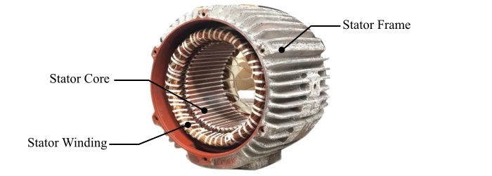
The stator frame is the outermost cover of the stator. It protects the internal parts like windings from mechanical and environmental damages.
The stator core is a hollow cylinder having slots on the inner periphery to insert stator windings. The stator of an electrical machine is made up of high-grade silicon steel laminations.
The stator windings are the coils made up of copper or aluminum wires. These windings are connected to the external electrical system. In the case of electric motor, the stator winding accepts electrical energy from the supply. In the case of electric generator, the stator winding supply electrical energy to the external electrical loads.
Functions of Stator in Electrical Macines
The stator of an electrical machine performs the following functions
- In an electric motor, the stator acts as the magnetic field system and produces the main field flux required for working of the motor.
- In an electric generator, the stator acts as the armature. It consists of stator or armature windings in which the emf and current is induced that is then supplied to the external electrical loads.
- It provides mechanical covering to the internal assembly of electrical machines.
Hence, this all about stator of an electrical machine. Overall, the stator of all electrical machine (motor or generator) has almost same construction. However, it performs different functions in motor and generators.
What is a Rotor in Electrical Machines?
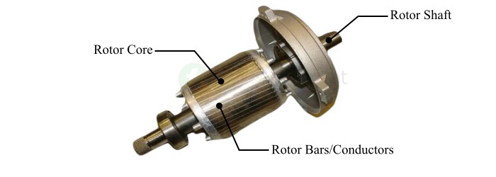
In electrical machines, the rotor is a moving or rotating part that can freely move on its own axis. The rotor of any electrical machine (motor or generator) consists of three main parts namely, rotor core, rotor winding, and rotor shaft.
The rotor core is a cylindrical shaped component made up of high-grade silicon steel laminations. It has slots on the outer periphery to insert rotor windings.
The rotor winding can be a coil or conductor made up of copper or aluminum. The rotor windings are wound on the rotor core.
The rotor shaft is a long rod to which the mechanical load or turbine is attached. The rotor core is mounted on the shaft. Hence, when a torque is produced in the rotor core, it also rotates the shaft.
Functions of Rotor in Electrical Machines
The rotor of electrical machines performs the following functions
- In electric motors, the rotor acts as the component that transforms electrical energy into rotational mechanical energy to drive the mechanical load like a fan. In other words, the rotor acts as the armature in electric motors and develops the working torque in the machine.
- In electric generators, the rotor acts as the magnetic field system and produces a rotating magnetic field required to induce an emf in the armature.
- In both types of electrical machines, motor and generator, the rotor in the moving part that rotates within the machine.
Types of Rotors in Electrical Machines
Different types of electrical machines have different types of rotor constructions and designs. The common types of rotors used in electrical machines are given below
- Squirrel Cage Rotor
- Wound Rotor or Slip-Ring Rotor
- Salient Pole Rotor
- Cylindrical Rotor
Let us discuss each type of rotor in detail along with its features.
Squirrel Cage Rotor
The squirrel cage rotor is a type of rotor commonly used in induction motors. It consists of a rotor core made up of thin silicon steel laminations. It has copper or aluminum conductors embedded in the surface of the core. These conductor bars are short-circuited at both ends with the help of metal end rings.
It is also important to note about the squirrel cage rotors that the conductor bars are slightly skewed along their length to reduce the fluctuation in the torque and the noise.
Advantages of Squirrel Case Rotor
The following are some key advantages of squirrel cage rotors
- These rotors can be used in a wide range of electric motors from a few watts to tens of megawatts.
- Squirrel cage rotors are simple to design.
- They are very strong in construction.
- Squirrel cage rotors can provide fairly constant speed operation from light load to full load.
- Squirrel cage rotors are easy to replace.
Applications of Squirrel Cage Rotor
Squirrel cage rotors are mainly employed in induction motors that are used in applications where self-starting and constant speed is desired. Some common applications of squirrel cage rotors are given as follows
- In motors used to drive centrifugal pumps.
- In motors used to drive industrial loads such as conveyors, pumps, compressors, etc.
- In electric motors used in fans and blowers, etc.
Wound Rotor or Slip-Ring Rotor
The wound rotor is another type of rotor used in three-phase induction motors. It is also called slip-ring rotor because the rotor windings are connected to external resistance through slip rings.
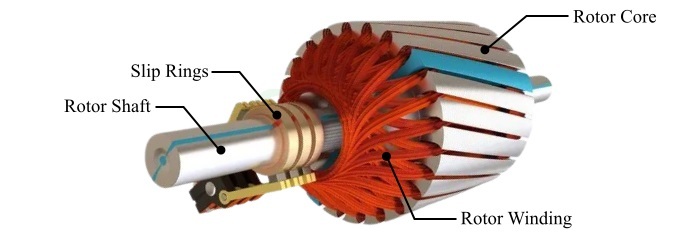
The wound rotor consists of a rotor core having slots on the outer periphery to insert rotor winding. These rotor windings are connected to the slip-rings wound on the rotor shaft. Where, the slip-rings are further connected to an external resistance.
Advantages of Wound Rotor
The following are some main advantages of wound rotors
- Wound rotor draws less starting current.
- Wound rotor can develop high starting torque.
- Wound rotors also have high overload capacity.
- Wound rotors provide easy speed control.
- The power factor of wound rotor can be improved easily.
Applications of Wound Rotor
The slip-ring or wound rotors are employed in induction motors that are used in applications where high starting torque and variable speed is required. Some common applications of wound rotors are given below
- In induction motors used in electric trains and locomotives.
- In motors used in cranes, lifts, and hoists.
Salient-Pole Rotor
A salient-pole rotor is a type of rotor used in synchronous motor and generators. This type of rotor has salient or projected poles mounted on a hub.
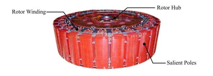
The salient-poles of the rotor are made up of thin steel laminations. The rotor windings are provided on these projected poles.
This type of rotor is larger in diameter and shorter in axial length. The salient-pole rotors are used in low-speed electrical machines. Also, they have non-uniform flux distribution in the air gap of the machine.
Advantages of Salient Pole Rotor
Some key benefits of using salient pole rotors in electrical machines are given below
- Salient pole rotors can be used with slow speed prime movers such as hydro-turbines.
- Salient pole rotors reduce the windage losses in the machine.
- Salient pole rotors also reduce the noise levels of the machines.
- These rotors reduce the bearing loads.
- Salient pole rotor provides good ventilation in the machine.
Applications of Salient Pole Rotor
Salient-pole rotors are mainly used in slow speed synchronous machines. Some practical applications of salient pole rotors are given below
- In alternators driven by water turbines.
- Salient pole rotors are also used in car alternators.
- These rotors are also used in diesel generators.
- Salient pole rotors are also used in synchronous motors operating at a speed between 100 RPM to 400 RPM.
Cylindrical Rotor
A cylindrical rotor is a type of rotor having a smooth cylindrical construction. It is made up of a solid forged steel having slots on the outer periphery to place rotor windings.

The cylindrical rotor is also known as non-salient pole rotor as it has no projected or salient poles. Since, this rotor has a smooth cylindrical construction, hence it creates a uniformly distributed air-gap between the stator and rotor inside the machine.
The cylindrical rotor has smaller diameter and larger axial length. Due to solid cylindrical design, this type of rotor has higher mechanical strength.
Advantages of Cylindrical Rotor
The following are key benefits of cylindrical rotors
- Cylindrical rotor has minimum windage losses due to smooth air gap.
- These rotors create a uniform air gap between stator and rotor in the machine.
- Cylindrical rotors produce less noise.
- There is no need of damper winding in the case of cylindrical rotor.
Applications of Cylindrical Rotor
Cylindrical rotors are used in electrical machines that operate at high speeds around 1500 RPM to 3000 RPM. Some practical applications of cylindrical rotors are given below
- High speed synchronous motors.
- Alternators driven by steam turbines, gas turbines, etc.
Conclusion
In conclusion, stator and rotor are two main components of any electrical machine. Where, the stator is the stationary part whereas the rotor is the moving part of the machine. The stator of all electrical machines has almost same construction. Whereas, different electrical machines have different types of rotors depending on their construction and requirements. In this detailed article on the stator and rotor of electrical machines, I have explained the construction and applications of stator and different types of rotors used in electrical machines.