- Electrical Machines - Home
- Basic Concepts
- Electromechanical Energy Conversion
- Energy Stored in Magnetic Field
- Singly-Excited and Doubly Excited Systems
- Rotating Electrical Machines
- Electrical Machines Types
- Faraday’s Laws of Electromagnetic Induction
- Concept of Induced EMF
- Fleming's Left Hand and Right Hand Rules
- Transformers
- Electrical Transformer
- Construction of Transformer
- EMF Equation of Transformer
- Turns Ratio and Voltage Transformation Ratio
- Ideal Transformer
- Practical Transformer
- Ideal and Practical Transformers
- Transformer on DC
- Losses in a Transformer
- Efficiency of Transformer
- 3-Phase Transformer
- Types of Transformers
- More on Transformers
- Transformer Working Principle
- Single-Phase Transformer Working Principle
- 3-Phase Transformer Principle
- 3-Phase Induction Motor Torque-Slip
- 3-Phase Induction Motor Torque-Speed
- 3-Phase Transformer Harmonics
- Double-Star Connection (3-6 Phase)
- Double-delta Connection (3-6 Phase)
- Transformer Ratios
- Voltage Regulation
- Delta-Star Connection (3-Phase)
- Star-Delta Connection (3-Phase)
- Autotransformer Conversion
- Back-to-back Test (Sumpner's Test)
- Transformer Voltage Drop
- Autotransformer Output
- Open and Short Circuit Test
- 3-Phase Autotransformer
- Star-Star Connection
- 6-Phase Diametrical Connections
- Circuit Test (Three-Winding)
- Potential Transformer
- Transformers Parallel Operation
- Open Delta (V-V) Connection
- Autotransformer
- Current Transformer
- No-Load Current Wave
- Transformer Inrush Current
- Transformer Vector Groups
- 3 to 12-Phase Transformers
- Scott-T Transformer Connection
- Transformer kVA Rating
- Three-Winding Transformer
- Delta-Delta Connection Transformer
- Transformer DC Supply Issue
- Equivalent Circuit Transformer
- Simplified Equivalent Circuit of Transformer
- Transformer No-Load Condition
- Transformer Load Condition
- OTI WTI Transformer
- CVT Transformer
- Isolation vs Regular Transformer
- Dry vs Oil-Filled
- DC Machines
- Construction of DC Machines
- Types of DC Machines
- Working Principle of DC Generator
- EMF Equation of DC Generator
- Derivation of EMF Equation DC Generator
- Types of DC Generators
- Working Principle of DC Motor
- Back EMF in DC Motor
- Types of DC Motors
- Losses in DC Machines
- Applications of DC Machines
- More on DC Machines
- DC Generator
- DC Generator Armature Reaction
- DC Generator Commutator Action
- Stepper vs DC Motors
- DC Shunt Generators Critical Resistance
- DC Machines Commutation
- DC Motor Characteristics
- Synchronous Generator Working Principle
- DC Generator Characteristics
- DC Generator Demagnetizing & Cross-Magnetizing
- DC Motor Voltage & Power Equations
- DC Generator Efficiency
- Electric Breaking of DC Motors
- DC Motor Efficiency
- Four Quadrant Operation of DC Motors
- Open Circuit Characteristics of DC Generators
- Voltage Build-Up in Self-Excited DC Generators
- Types of Armature Winding in DC Machines
- Torque in DC Motors
- Swinburne’s Test of DC Machine
- Speed Control of DC Shunt Motor
- Speed Control of DC Series Motor
- DC Motor of Speed Regulation
- Hopkinson's Test
- Permanent Magnet DC Motor
- Permanent Magnet Stepper Motor
- DC Servo Motor Theory
- DC Series vs Shunt Motor
- BLDC Motor vs PMSM Motor
- Induction Motors
- Introduction to Induction Motor
- Single-Phase Induction Motor
- 3-Phase Induction Motor
- Construction of 3-Phase Induction Motor
- 3-Phase Induction Motor on Load
- Characteristics of 3-Phase Induction Motor
- Speed Regulation and Speed Control
- Methods of Starting 3-Phase Induction Motors
- More on Induction Motors
- 3-Phase Induction Motor Working Principle
- 3-Phase Induction Motor Rotor Parameters
- Double Cage Induction Motor Equivalent Circuit
- Induction Motor Equivalent Circuit Models
- Slip Ring vs Squirrel Cage Induction Motors
- Single-Cage vs Double-Cage Induction Motor
- Induction Motor Equivalent Circuits
- Induction Motor Crawling & Cogging
- Induction Motor Blocked Rotor Test
- Induction Motor Circle Diagram
- 3-Phase Induction Motors Applications
- 3-Phase Induction Motors Torque Ratios
- Induction Motors Power Flow Diagram & Losses
- Determining Induction Motor Efficiency
- Induction Motor Speed Control by Pole-Amplitude Modulation
- Induction Motor Inverted or Rotor Fed
- High Torque Cage Motors
- Double-Cage Induction Motor Torque-Slip Characteristics
- 3-Phase Induction Motors Starting Torque
- 3-phase Induction Motor - Rotor Resistance Starter
- 3-phase Induction Motor Running Torque
- 3-Phase Induction Motor - Rotating Magnetic Field
- Isolated Induction Generator
- Capacitor-Start Induction Motor
- Capacitor-Start Capacitor-Run Induction Motor
- Winding EMFs in 3-Phase Induction Motors
- Split-Phase Induction Motor
- Shaded Pole Induction Motor
- Repulsion-Start Induction-Run Motor
- Repulsion Induction Motor
- PSC Induction Motor
- Single-Phase Induction Motor Performance Analysis
- Linear Induction Motor
- Single-Phase Induction Motor Testing
- 3-Phase Induction Motor Fault Types
- Synchronous Machines
- Introduction to 3-Phase Synchronous Machines
- Construction of Synchronous Machine
- Working of 3-Phase Alternator
- Armature Reaction in Synchronous Machines
- Output Power of 3-Phase Alternator
- Losses and Efficiency of an Alternator
- Losses and Efficiency of 3-Phase Alternator
- Working of 3-Phase Synchronous Motor
- Equivalent Circuit and Power Factor of Synchronous Motor
- Power Developed by Synchronous Motor
- More on Synchronous Machines
- AC Motor Types
- Induction Generator (Asynchronous Generator)
- Synchronous Speed Slip of 3-Phase Induction Motor
- Armature Reaction in Alternator at Leading Power Factor
- Armature Reaction in Alternator at Lagging Power Factor
- Stationary Armature vs Rotating Field Alternator Advantages
- Synchronous Impedance Method for Voltage Regulation
- Saturated & Unsaturated Synchronous Reactance
- Synchronous Reactance & Impedance
- Significance of Short Circuit Ratio in Alternator
- Hunting Effect Alternator
- Hydrogen Cooling in Synchronous Generators
- Excitation System of Synchronous Machine
- Equivalent Circuit Phasor Diagram of Synchronous Generator
- EMF Equation of Synchronous Generator
- Cooling Methods for Synchronous Generators
- Assumptions in Synchronous Impedance Method
- Armature Reaction at Unity Power Factor
- Voltage Regulation of Alternator
- Synchronous Generator with Infinite Bus Operation
- Zero Power Factor of Synchronous Generator
- Short Circuit Ratio Calculation of Synchronous Machines
- Speed-Frequency Relationship in Alternator
- Pitch Factor in Alternator
- Max Reactive Power in Synchronous Generators
- Power Flow Equations for Synchronous Generator
- Potier Triangle for Voltage Regulation in Alternators
- Parallel Operation of Alternators
- Load Sharing in Parallel Alternators
- Slip Test on Synchronous Machine
- Constant Flux Linkage Theorem
- Blondel's Two Reaction Theory
- Synchronous Machine Oscillations
- Ampere Turn Method for Voltage Regulation
- Salient Pole Synchronous Machine Theory
- Synchronization by Synchroscope
- Synchronization by Synchronizing Lamp Method
- Sudden Short Circuit in 3-Phase Alternator
- Short Circuit Transient in Synchronous Machines
- Power-Angle of Salient Pole Machines
- Prime-Mover Governor Characteristics
- Power Input of Synchronous Generator
- Power Output of Synchronous Generator
- Power Developed by Salient Pole Motor
- Phasor Diagrams of Cylindrical Rotor Moto
- Synchronous Motor Excitation Voltage Determination
- Hunting Synchronous Motor
- Self-Starting Synchronous Motor
- Unidirectional Torque Production in Synchronous Motor
- Effect of Load Change on Synchronous Motor
- Field Excitation Effect on Synchronous Motor
- Output Power of Synchronous Motor
- Input Power of Synchronous Motor
- V Curves & Inverted V Curves of Synchronous Motor
- Torque in Synchronous Motor
- Construction of 3-Phase Synchronous Motor
- Synchronous Motor
- Synchronous Condenser
- Power Flow in Synchronous Motor
- Types of Faults in Alternator
- Miscellaneous Topics
- Electrical Generator
- Determining Electric Motor Load
- Solid State Motor Starters
- Characteristics of Single-Phase Motor
- Types of AC Generators
- Three-Point Starter
- Four-Point Starter
- Ward Leonard Speed Control Method
- Pole Changing Method
- Stator Voltage Control Method
- DOL Starter
- Star-Delta Starter
- Hysteresis Motor
- 2-Phase & 3-Phase AC Servo Motors
- Repulsion Motor
- Reluctance Motor
- Stepper Motor
- PCB Motor
- Single-Stack Variable Reluctance Stepper Motor
- Schrage Motor
- Hybrid Schrage Motor
- Multi-Stack Variable Reluctance Stepper Motor
- Universal Motor
- Step Angle in Stepper Motor
- Stepper Motor Torque-Pulse Rate Characteristics
- Distribution Factor
- Electrical Machines Basic Terms
- Synchronizing Torque Coefficient
- Synchronizing Power Coefficient
- Metadyne
- Motor Soft Starter
- CVT vs PT
- Metering CT vs Protection CT
- Stator and Rotor in Electrical Machines
- Electric Motor Winding
- Electric Motor
- Useful Resources
- Quick Guide
- Resources
- Discussion
Three-Phase Induction Motor
As the name suggests, a three-phase induction motor is one which works on three-phase AC supply, and converts three-phase AC electricity into mechanical energy. Three-phase induction motors are the most extensively used electric motors in industries. These motors run at almost a constant speed from no-load to full-load, i.e., they have good speed regulation. Although the speed of three-phase induction motors depends on the supply frequency and number of poles in the machine and therefore, it is quite difficult to change their speed.

Just like any other electric motor, a typical three-phase induction motor also consists of two main parts namely stator and rotor. The stator is a stationary part and carries a three-phase winding, called stator winding. The rotor is a rotating part of the motor and carries a short-circuited winding, called rotor winding.
The stator winding of a three-phase induction motor is fed from a three-phase balanced AC supply, while the rotor winding derives its working voltage and power from the stator winding via electromagnetic induction. This is why, it is named so.
A three-phase induction motor may be considered to be a three-phase transformer with a rotating secondary winding. Therefore, it could be described as a transformer-type AC machine. The only difference is that the induction motor converts electricity into mechanical energy.
Types of Three-Phase Induction Motors
According to the rotor construction, three-phase induction motors are classified into the following two basic types −
- Squirrel-Cage Induction Motor
- Slip-Ring Induction Motor
Squirrel Cage Induction Motor Starting Methods
The following four methods are available for starting squirrel cage motors −
Direct On-Line (D.O.L.) Starting
As the name suggests, the Induction Motor is started by connecting it directly to three-phase supply. In this method, the motor draws a high starting current (about 4 to 7 times of the rated current) and at low power factor. Therefore, DOL starting is suitable for relatively small motors (up to 10 kW).

Stator Resistance Starting
In this method, external resistance is connected in series with each phase of the stator winding during starting. The external resistance causes voltage to drop across it so that reduced voltage available across the motor terminals. Hence, the starting current is reduced. The starting external resistances are gradually cut out in steps from the stator circuit, as the motor accelerates. When the motor attains the rated speed, the starting resistances are completely cut out and full line voltage is applied across the motor terminals.
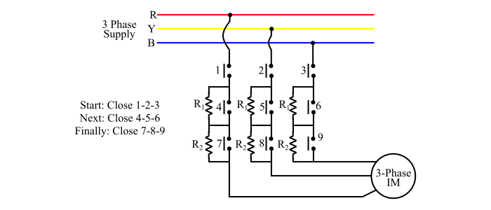
This method has two drawbacks. First, the reduced voltage during starting reduces the starting torque and hence increases acceleration time. Secondly, a lot power is wasted in the starting resistances.
Autotransformer Starting
In this method, an autotransformer is used to reduce the starting voltage of the induction motor. The tapings of the autotransformer is so set that when it is in the circuit, 60 to 80 % of the line voltage is applied to motor during starting and then connecting it to the full-line voltage as the motor attains a sufficient speed.
At the instant of starting, the change-over switch is connected to "Start". This supplies the reduced voltage to the motor through the autotransformer. Consequently, the starting current is limited to safe value. When the motor attains about 80% of rated-speed, the change-over switch is now thrown to "Run". This removes the autotransformer from the circuit and full line voltage is applied across the motor terminals.
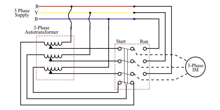
The autotransformer starting has many advantages such as low power loss, low starting current etc. This method is used for large motors over 25 hp.
Star-Delta Starting
In star-delta starting method of squirrel cage induction motor, the motor started in star and run in delta, i.e. the stator winding of the motor is designed for delta operation and is connected in star during starting. When the motor attains sufficient speed, the connections are changed to delta.
The six leads of stator winding of the motor are connected to a change-over switch. At the time of starting, the change-over switch is switched to "Star" which connects the stator windings in star. Thus, each phase gets V/√3 volts, where V is the three phase line voltage. This reduces the starting current. When the motor attains 80% of rated speed, the changeover switch is switched to "Delta" which connects the stator windings in delta. Now, each phase gets full line voltage.
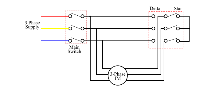
The principle disadvantage of this method is large reduction in stating torque due to reduced voltage in the star connection at the instant of starting. The star-delta starting is used for medium size motors up to 25 hp.
Slip Ring Induction Motor Starting Methods
The following four methods are used to start a slip ring induction motor −
- Direct On-Line (D.O.L.) Starting
- Stator-Resistance Starting
- Autotransformer Starting
- Rotor-Resistance Starting
The DOL starting, Stator-Resistance starting and Autotransformer starting are same as for the squirrel cage induction motor (as discussed above)
In industrial applications, the slip ring induction motor are mainly started using rotor-resistance method.
Rotor Resistance Starting
In this method, a star connected variable resistance is connected in the rotor circuit through slip-rings. The full voltage is applied to the stator windings.
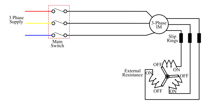
At the instant of starting, the handle of variable resistance (rheostat) is set to "OFF" position. This inserts maximum resistance in series with the each phase of the rotor circuit. This reduces the starting current and at the same time starting torque is increased due to external rotor resistance.
As the motor accelerates, the external resistance is gradually removed from the rotor circuit. When the motor attains rated speed, the handle is switched in the "ON" position, this removes the whole external resistance from the rotor circuit.
Advantages of Three-Phase Induction Motors
Here is a list of some of the major advantages of three-phase induction motors −
- The design and construction of three-phase induction motors are quite simple.
- They have robust construction.
- Three-phase induction motors require less maintenance.
- Three-phase induction motors have self-starting property.
- These motors have reasonably good power factor.
- Three-phase induction motors are more economical.
- They have high efficiency.
Disadvantages of Three-Phase Induction Motors
The major disadvantages of three-phase induction motors are listed below −
- Three-phase induction motors are essentially constant speed motors, and require complex mechanism to change the speed.
- Three-phase induction motors always work on lagging power factor.
- These motors draw very high starting current.
Applications of Three-Phase Induction Motors
The major applications of three-phase induction motors are given below −
- The squirrel-cage type three-phase induction motors are suitable for driving blowers, fans, machine tools, centrifugal pumps, etc.
- Three-phase induction motors are also used for driving different industrial load like compressors, crushers, conveyors, reciprocating pumps, etc.
- The slip-ring induction motors are best suited for driving loads that require high starting toque like crushers, plungers, cranes, elevators, hoists, conveyors, etc.