- Electrical Machines - Home
- Basic Concepts
- Electromechanical Energy Conversion
- Energy Stored in Magnetic Field
- Singly-Excited and Doubly Excited Systems
- Rotating Electrical Machines
- Electrical Machines Types
- Faraday’s Laws of Electromagnetic Induction
- Concept of Induced EMF
- Fleming's Left Hand and Right Hand Rules
- Transformers
- Electrical Transformer
- Construction of Transformer
- EMF Equation of Transformer
- Turns Ratio and Voltage Transformation Ratio
- Ideal Transformer
- Practical Transformer
- Ideal and Practical Transformers
- Transformer on DC
- Losses in a Transformer
- Efficiency of Transformer
- 3-Phase Transformer
- Types of Transformers
- More on Transformers
- Transformer Working Principle
- Single-Phase Transformer Working Principle
- 3-Phase Transformer Principle
- 3-Phase Induction Motor Torque-Slip
- 3-Phase Induction Motor Torque-Speed
- 3-Phase Transformer Harmonics
- Double-Star Connection (3-6 Phase)
- Double-delta Connection (3-6 Phase)
- Transformer Ratios
- Voltage Regulation
- Delta-Star Connection (3-Phase)
- Star-Delta Connection (3-Phase)
- Autotransformer Conversion
- Back-to-back Test (Sumpner's Test)
- Transformer Voltage Drop
- Autotransformer Output
- Open and Short Circuit Test
- 3-Phase Autotransformer
- Star-Star Connection
- 6-Phase Diametrical Connections
- Circuit Test (Three-Winding)
- Potential Transformer
- Transformers Parallel Operation
- Open Delta (V-V) Connection
- Autotransformer
- Current Transformer
- No-Load Current Wave
- Transformer Inrush Current
- Transformer Vector Groups
- 3 to 12-Phase Transformers
- Scott-T Transformer Connection
- Transformer kVA Rating
- Three-Winding Transformer
- Delta-Delta Connection Transformer
- Transformer DC Supply Issue
- Equivalent Circuit Transformer
- Simplified Equivalent Circuit of Transformer
- Transformer No-Load Condition
- Transformer Load Condition
- OTI WTI Transformer
- CVT Transformer
- Isolation vs Regular Transformer
- Dry vs Oil-Filled
- DC Machines
- Construction of DC Machines
- Types of DC Machines
- Working Principle of DC Generator
- EMF Equation of DC Generator
- Derivation of EMF Equation DC Generator
- Types of DC Generators
- Working Principle of DC Motor
- Back EMF in DC Motor
- Types of DC Motors
- Losses in DC Machines
- Applications of DC Machines
- More on DC Machines
- DC Generator
- DC Generator Armature Reaction
- DC Generator Commutator Action
- Stepper vs DC Motors
- DC Shunt Generators Critical Resistance
- DC Machines Commutation
- DC Motor Characteristics
- Synchronous Generator Working Principle
- DC Generator Characteristics
- DC Generator Demagnetizing & Cross-Magnetizing
- DC Motor Voltage & Power Equations
- DC Generator Efficiency
- Electric Breaking of DC Motors
- DC Motor Efficiency
- Four Quadrant Operation of DC Motors
- Open Circuit Characteristics of DC Generators
- Voltage Build-Up in Self-Excited DC Generators
- Types of Armature Winding in DC Machines
- Torque in DC Motors
- Swinburne’s Test of DC Machine
- Speed Control of DC Shunt Motor
- Speed Control of DC Series Motor
- DC Motor of Speed Regulation
- Hopkinson's Test
- Permanent Magnet DC Motor
- Permanent Magnet Stepper Motor
- DC Servo Motor Theory
- DC Series vs Shunt Motor
- BLDC Motor vs PMSM Motor
- Induction Motors
- Introduction to Induction Motor
- Single-Phase Induction Motor
- 3-Phase Induction Motor
- Construction of 3-Phase Induction Motor
- 3-Phase Induction Motor on Load
- Characteristics of 3-Phase Induction Motor
- Speed Regulation and Speed Control
- Methods of Starting 3-Phase Induction Motors
- More on Induction Motors
- 3-Phase Induction Motor Working Principle
- 3-Phase Induction Motor Rotor Parameters
- Double Cage Induction Motor Equivalent Circuit
- Induction Motor Equivalent Circuit Models
- Slip Ring vs Squirrel Cage Induction Motors
- Single-Cage vs Double-Cage Induction Motor
- Induction Motor Equivalent Circuits
- Induction Motor Crawling & Cogging
- Induction Motor Blocked Rotor Test
- Induction Motor Circle Diagram
- 3-Phase Induction Motors Applications
- 3-Phase Induction Motors Torque Ratios
- Induction Motors Power Flow Diagram & Losses
- Determining Induction Motor Efficiency
- Induction Motor Speed Control by Pole-Amplitude Modulation
- Induction Motor Inverted or Rotor Fed
- High Torque Cage Motors
- Double-Cage Induction Motor Torque-Slip Characteristics
- 3-Phase Induction Motors Starting Torque
- 3-phase Induction Motor - Rotor Resistance Starter
- 3-phase Induction Motor Running Torque
- 3-Phase Induction Motor - Rotating Magnetic Field
- Isolated Induction Generator
- Capacitor-Start Induction Motor
- Capacitor-Start Capacitor-Run Induction Motor
- Winding EMFs in 3-Phase Induction Motors
- Split-Phase Induction Motor
- Shaded Pole Induction Motor
- Repulsion-Start Induction-Run Motor
- Repulsion Induction Motor
- PSC Induction Motor
- Single-Phase Induction Motor Performance Analysis
- Linear Induction Motor
- Single-Phase Induction Motor Testing
- 3-Phase Induction Motor Fault Types
- Synchronous Machines
- Introduction to 3-Phase Synchronous Machines
- Construction of Synchronous Machine
- Working of 3-Phase Alternator
- Armature Reaction in Synchronous Machines
- Output Power of 3-Phase Alternator
- Losses and Efficiency of an Alternator
- Losses and Efficiency of 3-Phase Alternator
- Working of 3-Phase Synchronous Motor
- Equivalent Circuit and Power Factor of Synchronous Motor
- Power Developed by Synchronous Motor
- More on Synchronous Machines
- AC Motor Types
- Induction Generator (Asynchronous Generator)
- Synchronous Speed Slip of 3-Phase Induction Motor
- Armature Reaction in Alternator at Leading Power Factor
- Armature Reaction in Alternator at Lagging Power Factor
- Stationary Armature vs Rotating Field Alternator Advantages
- Synchronous Impedance Method for Voltage Regulation
- Saturated & Unsaturated Synchronous Reactance
- Synchronous Reactance & Impedance
- Significance of Short Circuit Ratio in Alternator
- Hunting Effect Alternator
- Hydrogen Cooling in Synchronous Generators
- Excitation System of Synchronous Machine
- Equivalent Circuit Phasor Diagram of Synchronous Generator
- EMF Equation of Synchronous Generator
- Cooling Methods for Synchronous Generators
- Assumptions in Synchronous Impedance Method
- Armature Reaction at Unity Power Factor
- Voltage Regulation of Alternator
- Synchronous Generator with Infinite Bus Operation
- Zero Power Factor of Synchronous Generator
- Short Circuit Ratio Calculation of Synchronous Machines
- Speed-Frequency Relationship in Alternator
- Pitch Factor in Alternator
- Max Reactive Power in Synchronous Generators
- Power Flow Equations for Synchronous Generator
- Potier Triangle for Voltage Regulation in Alternators
- Parallel Operation of Alternators
- Load Sharing in Parallel Alternators
- Slip Test on Synchronous Machine
- Constant Flux Linkage Theorem
- Blondel's Two Reaction Theory
- Synchronous Machine Oscillations
- Ampere Turn Method for Voltage Regulation
- Salient Pole Synchronous Machine Theory
- Synchronization by Synchroscope
- Synchronization by Synchronizing Lamp Method
- Sudden Short Circuit in 3-Phase Alternator
- Short Circuit Transient in Synchronous Machines
- Power-Angle of Salient Pole Machines
- Prime-Mover Governor Characteristics
- Power Input of Synchronous Generator
- Power Output of Synchronous Generator
- Power Developed by Salient Pole Motor
- Phasor Diagrams of Cylindrical Rotor Moto
- Synchronous Motor Excitation Voltage Determination
- Hunting Synchronous Motor
- Self-Starting Synchronous Motor
- Unidirectional Torque Production in Synchronous Motor
- Effect of Load Change on Synchronous Motor
- Field Excitation Effect on Synchronous Motor
- Output Power of Synchronous Motor
- Input Power of Synchronous Motor
- V Curves & Inverted V Curves of Synchronous Motor
- Torque in Synchronous Motor
- Construction of 3-Phase Synchronous Motor
- Synchronous Motor
- Synchronous Condenser
- Power Flow in Synchronous Motor
- Types of Faults in Alternator
- Miscellaneous Topics
- Electrical Generator
- Determining Electric Motor Load
- Solid State Motor Starters
- Characteristics of Single-Phase Motor
- Types of AC Generators
- Three-Point Starter
- Four-Point Starter
- Ward Leonard Speed Control Method
- Pole Changing Method
- Stator Voltage Control Method
- DOL Starter
- Star-Delta Starter
- Hysteresis Motor
- 2-Phase & 3-Phase AC Servo Motors
- Repulsion Motor
- Reluctance Motor
- Stepper Motor
- PCB Motor
- Single-Stack Variable Reluctance Stepper Motor
- Schrage Motor
- Hybrid Schrage Motor
- Multi-Stack Variable Reluctance Stepper Motor
- Universal Motor
- Step Angle in Stepper Motor
- Stepper Motor Torque-Pulse Rate Characteristics
- Distribution Factor
- Electrical Machines Basic Terms
- Synchronizing Torque Coefficient
- Synchronizing Power Coefficient
- Metadyne
- Motor Soft Starter
- CVT vs PT
- Metering CT vs Protection CT
- Stator and Rotor in Electrical Machines
- Electric Motor Winding
- Electric Motor
- Useful Resources
- Quick Guide
- Resources
- Discussion
Singly-Excited and Doubly Excited Systems
Excitation means providing electrical input to an electromechanical energy conversion device such as electric motors. The excitation produces working magnetic field in the electrical machine. Some electrical machines require single electrical input whereas some others require two electrical inputs.
Therefore, depending on the number of electrical inputs to electromechanical energy conversion systems, they can be classified into two types −
Singly-Excited System
Doubly-Excited System
Singly Excited System
As its name implies, a singly-excited system is one which consists of only one electrically energized coil to produce working magnetic field in the machine or any other electromechanical energy conversion device. Hence, the singly-excited system requires only one electrical input.
A singly excited system consists of coil wound around a magnetic core and is connected to a voltage source so that it produces a magnetic field. Due to this magnetic field, the rotor (or moving part) which is made up of ferromagnetic material experiences a torque which move it towards a region where the magnetic field is stronger, i.e., the torque exerted on the rotor tries to position it such that it shows minimum reluctance in the path of magnetic flux. The reluctance depends upon the rotor angle. This torque is known as reluctance torque or saliency torque because it is caused due to saliency of the rotor.
Analysis of Singly Excited System
We made following assumption to analyze the singly-excited system −
For any rotor position, the relationship between flux linkage ($\psi $) and current ($\mathit{i}$) is linear.
The coil has negligible leakage flux, which means all the magnetic flux flows through the main magnetic path.
Hysteresis loss and eddy-current loss are neglected.
All the electric fields are neglected and the magnetic field is predominating.
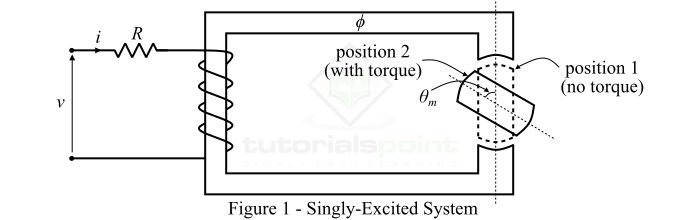
Consider the singly-excited system as shown in Figure-1. If R is the resistance of the coil circuit, the by applying KVL, we can write the voltage equation as,
$$\mathrm{\mathit{v\:=\:iR\:+\:\frac{\mathit{d\psi }}{\mathit{dt}}}\cdot \cdot \cdot (1)}$$
On multiplying equation (1) by current $\mathit{i}$, we have,
$$\mathrm{\mathit{vi\:=\:i^{\mathrm{2}}R\:+\mathit{i}\:\frac{\mathit{d\psi }}{\mathit{dt}}}\cdot \cdot \cdot (2)}$$
We are assuming initial conditions of the system zero and integrating the equation (2) on both side with respect to time, we obtain,
$$\mathrm{\int_{0}^{\mathit{T}}\mathit{vi\:dt}\:=\:\int_{0}^{\mathit{T}}\left ( i^{\mathrm{2}}\mathit{R}\:+\mathit{i}\:\frac{\mathit{d\psi }}{\mathit{dt}} \right )\mathit{dt}}$$
$$\mathrm{\Rightarrow\int_{0}^{\mathit{T}}\mathit{vi\:dt}\:=\:\int_{0}^{\mathit{T}}\mathit{i^{\mathrm{2}}R\:dt}\:+\:\int_{0}^{\psi }\mathit{i\:d\psi }\cdot \cdot \cdot (3)}$$
Equation-3 gives the total electrical energy input the singly-excited system and it is equal to two parts namely,
First part is the electrical loss ($\mathit{W_{el}}$).
Second part is the useful electrical energy which is the sum of field energy ($\mathit{W_{f}}$) and output mechanical energy ($\mathit{W_{m}}$).
Therefore, symbolically we may express the Equation-3 as,
$$\mathrm{\mathit{W_{in}}\:=\:\mathit{W_{el}}\:=\:\left (\mathit{W_{f}} \:+\:\mathit{W_{m}} \right )}\cdot \cdot \cdot (4)$$
The energy stored in the magnetic field of a singly-excited system is given by,
$$\mathrm{\mathit{W_{f}}\:=\: \int_{0}^{\psi }\mathit{i\:d\psi }\:=\:\int_{0}^{\psi }\frac{\psi }{\mathit{L}}\mathit{d\psi }\:=\:\frac{\psi ^{\mathrm{2}}}{2\mathit{L}}\cdot \cdot \cdot (5)}$$
For a rotor movement, where the rotor angle is $\mathit{\theta _{m}}$, the electromagnetic torque developed in the singly-excited system is given by,
$$\mathrm{\mathit{\tau _{e}}\:=\:\frac{\mathit{i^{\mathrm{2}}}}{\mathrm{2}}\frac{\mathit{\partial L}}{\mathit{\partial \theta _{m}}}\cdot \cdot \cdot (6)}$$
The most common examples of singly-excited system are induction motors, PMMC instruments, etc.
Doubly Excited System
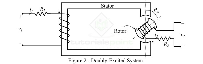
An electromagnetic system is one which has two independent coils to produce magnetic field is known as doubly-excited system. Therefore, a doubly-excited system requires two separate electrical inputs.
Analysis of Doubly Excited System
A doubly-excited system consists of two main parts namely a stator and a rotor as shown in Figure-2. Here, the stator is wound with a coil having a resistance R1 and the rotor is wound with a coil of resistance R2. Therefore, there are two separated windings which are excited by two independent voltage sources.
In order to analyze the double-excited system, the following assumption are made −
For any rotor position the relationship between flux-linkage ($\psi$) and current is linear.
Hysteresis and eddy current losses are neglected.
The coils have negligible leakage flux.
The electric fields are neglected and the magnetic fields are predominating.
The magnetic flux linkages to two windings are given by,
$$\mathrm{\psi _{\mathrm{1}}\:=\:\mathit{L_{\mathrm{1}}i_{\mathrm{1}}}\:+\:\mathit{Mi_{\mathrm{2}}}}\cdot \cdot \cdot (7)$$
$$\mathrm{\psi _{\mathrm{2}}\:=\:\mathit{L_{\mathrm{2}}i_{\mathrm{2}}}\:+\:\mathit{Mi_{\mathrm{2}}}}\cdot \cdot \cdot (8)$$
Where, M is the mutual inductance between two windings.
By applying KVL, we can write the equations of instantaneous voltage for two coils as,
$$\mathrm{\mathit{v}_{\mathrm{1}}\:=\:\mathit{i_{\mathrm{1}}R_{\mathrm{1}}}\:+\:\frac{\mathit{d\psi _{\mathrm{1}}}}{\mathit{dt}}}\cdot \cdot \cdot (9)$$
$$\mathrm{\mathit{v}_{\mathrm{2}}\:=\:\mathit{i_{\mathrm{2}}R_{\mathrm{2}}}\:+\:\frac{\mathit{d\psi _{\mathrm{2}}}}{\mathit{dt}}}\cdot \cdot \cdot (10)$$
In case of doubly-excited system, the energy stored in the magnetic field is given by,
$$\mathrm{\mathit{W_{f}}\:=\:\frac{1}{2}\mathit{L_{\mathrm{1}}i_{\mathrm{1}}^{\mathrm{2}}}\:+\:\frac{1}{2}\mathit{L_{\mathrm{2}}i_{\mathrm{2}}^{\mathrm{2}}}\:+\:\mathit{Mi_{\mathrm{1}}i_{\mathrm{2}}}\cdot \cdot \cdot (11)}$$
And, the electromagnetic torque developed in the doubly excited system is given by,
$$\mathrm{\mathit{\tau _{e}}\:=\:\frac{\mathit{i_{\mathrm{1}}^{\mathrm{2}}}}{\mathrm{2}}\frac{\mathit{dL_{\mathrm{1}}}}{\mathit{d\theta _{m}}}\:+\:\frac{\mathit{i_{\mathrm{2}}^{\mathrm{2}}}}{\mathrm{2}}\frac{\mathit{dL_{\mathrm{2}}}}{\mathit{d\theta _{m}}}\:+\:\mathit{i_{\mathrm{1}}i_{\mathrm{2}}}\frac{\mathit{dM}}{\mathit{d\theta _{m}}}\cdot \cdot \cdot (12)}$$
In Equation-12, the first two terms are the reluctance torque and the last term gives the co-alignment torque due to interaction of two fields.
The practical examples of doubly-excited system are synchronous machines, tachometer, separately-excited DC machines, etc.