- Electrical Machines - Home
- Basic Concepts
- Electromechanical Energy Conversion
- Energy Stored in Magnetic Field
- Singly-Excited and Doubly Excited Systems
- Rotating Electrical Machines
- Electrical Machines Types
- Faraday’s Laws of Electromagnetic Induction
- Concept of Induced EMF
- Fleming's Left Hand and Right Hand Rules
- Transformers
- Electrical Transformer
- Construction of Transformer
- EMF Equation of Transformer
- Turns Ratio and Voltage Transformation Ratio
- Ideal Transformer
- Practical Transformer
- Ideal and Practical Transformers
- Transformer on DC
- Losses in a Transformer
- Efficiency of Transformer
- 3-Phase Transformer
- Types of Transformers
- More on Transformers
- Transformer Working Principle
- Single-Phase Transformer Working Principle
- 3-Phase Transformer Principle
- 3-Phase Induction Motor Torque-Slip
- 3-Phase Induction Motor Torque-Speed
- 3-Phase Transformer Harmonics
- Double-Star Connection (3-6 Phase)
- Double-delta Connection (3-6 Phase)
- Transformer Ratios
- Voltage Regulation
- Delta-Star Connection (3-Phase)
- Star-Delta Connection (3-Phase)
- Autotransformer Conversion
- Back-to-back Test (Sumpner's Test)
- Transformer Voltage Drop
- Autotransformer Output
- Open and Short Circuit Test
- 3-Phase Autotransformer
- Star-Star Connection
- 6-Phase Diametrical Connections
- Circuit Test (Three-Winding)
- Potential Transformer
- Transformers Parallel Operation
- Open Delta (V-V) Connection
- Autotransformer
- Current Transformer
- No-Load Current Wave
- Transformer Inrush Current
- Transformer Vector Groups
- 3 to 12-Phase Transformers
- Scott-T Transformer Connection
- Transformer kVA Rating
- Three-Winding Transformer
- Delta-Delta Connection Transformer
- Transformer DC Supply Issue
- Equivalent Circuit Transformer
- Simplified Equivalent Circuit of Transformer
- Transformer No-Load Condition
- Transformer Load Condition
- OTI WTI Transformer
- CVT Transformer
- Isolation vs Regular Transformer
- Dry vs Oil-Filled
- DC Machines
- Construction of DC Machines
- Types of DC Machines
- Working Principle of DC Generator
- EMF Equation of DC Generator
- Derivation of EMF Equation DC Generator
- Types of DC Generators
- Working Principle of DC Motor
- Back EMF in DC Motor
- Types of DC Motors
- Losses in DC Machines
- Applications of DC Machines
- More on DC Machines
- DC Generator
- DC Generator Armature Reaction
- DC Generator Commutator Action
- Stepper vs DC Motors
- DC Shunt Generators Critical Resistance
- DC Machines Commutation
- DC Motor Characteristics
- Synchronous Generator Working Principle
- DC Generator Characteristics
- DC Generator Demagnetizing & Cross-Magnetizing
- DC Motor Voltage & Power Equations
- DC Generator Efficiency
- Electric Breaking of DC Motors
- DC Motor Efficiency
- Four Quadrant Operation of DC Motors
- Open Circuit Characteristics of DC Generators
- Voltage Build-Up in Self-Excited DC Generators
- Types of Armature Winding in DC Machines
- Torque in DC Motors
- Swinburne’s Test of DC Machine
- Speed Control of DC Shunt Motor
- Speed Control of DC Series Motor
- DC Motor of Speed Regulation
- Hopkinson's Test
- Permanent Magnet DC Motor
- Permanent Magnet Stepper Motor
- DC Servo Motor Theory
- DC Series vs Shunt Motor
- BLDC Motor vs PMSM Motor
- Induction Motors
- Introduction to Induction Motor
- Single-Phase Induction Motor
- 3-Phase Induction Motor
- Construction of 3-Phase Induction Motor
- 3-Phase Induction Motor on Load
- Characteristics of 3-Phase Induction Motor
- Speed Regulation and Speed Control
- Methods of Starting 3-Phase Induction Motors
- More on Induction Motors
- 3-Phase Induction Motor Working Principle
- 3-Phase Induction Motor Rotor Parameters
- Double Cage Induction Motor Equivalent Circuit
- Induction Motor Equivalent Circuit Models
- Slip Ring vs Squirrel Cage Induction Motors
- Single-Cage vs Double-Cage Induction Motor
- Induction Motor Equivalent Circuits
- Induction Motor Crawling & Cogging
- Induction Motor Blocked Rotor Test
- Induction Motor Circle Diagram
- 3-Phase Induction Motors Applications
- 3-Phase Induction Motors Torque Ratios
- Induction Motors Power Flow Diagram & Losses
- Determining Induction Motor Efficiency
- Induction Motor Speed Control by Pole-Amplitude Modulation
- Induction Motor Inverted or Rotor Fed
- High Torque Cage Motors
- Double-Cage Induction Motor Torque-Slip Characteristics
- 3-Phase Induction Motors Starting Torque
- 3-phase Induction Motor - Rotor Resistance Starter
- 3-phase Induction Motor Running Torque
- 3-Phase Induction Motor - Rotating Magnetic Field
- Isolated Induction Generator
- Capacitor-Start Induction Motor
- Capacitor-Start Capacitor-Run Induction Motor
- Winding EMFs in 3-Phase Induction Motors
- Split-Phase Induction Motor
- Shaded Pole Induction Motor
- Repulsion-Start Induction-Run Motor
- Repulsion Induction Motor
- PSC Induction Motor
- Single-Phase Induction Motor Performance Analysis
- Linear Induction Motor
- Single-Phase Induction Motor Testing
- 3-Phase Induction Motor Fault Types
- Synchronous Machines
- Introduction to 3-Phase Synchronous Machines
- Construction of Synchronous Machine
- Working of 3-Phase Alternator
- Armature Reaction in Synchronous Machines
- Output Power of 3-Phase Alternator
- Losses and Efficiency of an Alternator
- Losses and Efficiency of 3-Phase Alternator
- Working of 3-Phase Synchronous Motor
- Equivalent Circuit and Power Factor of Synchronous Motor
- Power Developed by Synchronous Motor
- More on Synchronous Machines
- AC Motor Types
- Induction Generator (Asynchronous Generator)
- Synchronous Speed Slip of 3-Phase Induction Motor
- Armature Reaction in Alternator at Leading Power Factor
- Armature Reaction in Alternator at Lagging Power Factor
- Stationary Armature vs Rotating Field Alternator Advantages
- Synchronous Impedance Method for Voltage Regulation
- Saturated & Unsaturated Synchronous Reactance
- Synchronous Reactance & Impedance
- Significance of Short Circuit Ratio in Alternator
- Hunting Effect Alternator
- Hydrogen Cooling in Synchronous Generators
- Excitation System of Synchronous Machine
- Equivalent Circuit Phasor Diagram of Synchronous Generator
- EMF Equation of Synchronous Generator
- Cooling Methods for Synchronous Generators
- Assumptions in Synchronous Impedance Method
- Armature Reaction at Unity Power Factor
- Voltage Regulation of Alternator
- Synchronous Generator with Infinite Bus Operation
- Zero Power Factor of Synchronous Generator
- Short Circuit Ratio Calculation of Synchronous Machines
- Speed-Frequency Relationship in Alternator
- Pitch Factor in Alternator
- Max Reactive Power in Synchronous Generators
- Power Flow Equations for Synchronous Generator
- Potier Triangle for Voltage Regulation in Alternators
- Parallel Operation of Alternators
- Load Sharing in Parallel Alternators
- Slip Test on Synchronous Machine
- Constant Flux Linkage Theorem
- Blondel's Two Reaction Theory
- Synchronous Machine Oscillations
- Ampere Turn Method for Voltage Regulation
- Salient Pole Synchronous Machine Theory
- Synchronization by Synchroscope
- Synchronization by Synchronizing Lamp Method
- Sudden Short Circuit in 3-Phase Alternator
- Short Circuit Transient in Synchronous Machines
- Power-Angle of Salient Pole Machines
- Prime-Mover Governor Characteristics
- Power Input of Synchronous Generator
- Power Output of Synchronous Generator
- Power Developed by Salient Pole Motor
- Phasor Diagrams of Cylindrical Rotor Moto
- Synchronous Motor Excitation Voltage Determination
- Hunting Synchronous Motor
- Self-Starting Synchronous Motor
- Unidirectional Torque Production in Synchronous Motor
- Effect of Load Change on Synchronous Motor
- Field Excitation Effect on Synchronous Motor
- Output Power of Synchronous Motor
- Input Power of Synchronous Motor
- V Curves & Inverted V Curves of Synchronous Motor
- Torque in Synchronous Motor
- Construction of 3-Phase Synchronous Motor
- Synchronous Motor
- Synchronous Condenser
- Power Flow in Synchronous Motor
- Types of Faults in Alternator
- Miscellaneous Topics
- Electrical Generator
- Determining Electric Motor Load
- Solid State Motor Starters
- Characteristics of Single-Phase Motor
- Types of AC Generators
- Three-Point Starter
- Four-Point Starter
- Ward Leonard Speed Control Method
- Pole Changing Method
- Stator Voltage Control Method
- DOL Starter
- Star-Delta Starter
- Hysteresis Motor
- 2-Phase & 3-Phase AC Servo Motors
- Repulsion Motor
- Reluctance Motor
- Stepper Motor
- PCB Motor
- Single-Stack Variable Reluctance Stepper Motor
- Schrage Motor
- Hybrid Schrage Motor
- Multi-Stack Variable Reluctance Stepper Motor
- Universal Motor
- Step Angle in Stepper Motor
- Stepper Motor Torque-Pulse Rate Characteristics
- Distribution Factor
- Electrical Machines Basic Terms
- Synchronizing Torque Coefficient
- Synchronizing Power Coefficient
- Metadyne
- Motor Soft Starter
- CVT vs PT
- Metering CT vs Protection CT
- Stator and Rotor in Electrical Machines
- Electric Motor Winding
- Electric Motor
- Useful Resources
- Quick Guide
- Resources
- Discussion
Open Circuit and Short Circuit Test of Transformer
The open-circuit test and the short-circuit test being performed on a transformer to determine the circuit parameters, efficiency and the voltage regulation without actual loaded of the transformer. The open-circuit and short-circuit tests give more accurate results than those are obtained by performing the measurbents on a fully loaded transformer. The principle of advantage of these tests is the power consumption is very small as compared to the full-load output of the transformer.
Open-Circuit Test of Transformer
The circuit arrangbent for the open-circuit test of a transformer is shown in the figure. In this test the high voltage side of the transformer is left open, i.e., the open circuit test is to be performer on the low-voltage side of the transformer. The open-circuit test is conducted to determine the core or iron losses and the no-load circuit parameters R0 and Xm of the transformer.
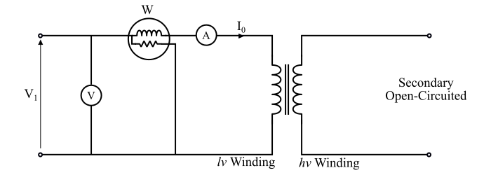
Now, in the connection diagram, a voltmeter (V), an ammeter (A) and a wattmeter (W) are connected in the primary side (which is low voltage (lv) winding of the given transformer) and the low-voltage winding is supplied at rated primary voltage and the frequency of the transformer. Thus, the reading of the voltmeter (V) shows the rated voltage V1 of the primary winding.
As the transformer is on no-load, i.e., the secondary winding is open circuited so a very small current I0 (called no-load current), flows in the primary winding. Therefore, the reading of the ammeter (A) shows the no-load current (I0) of the transformer. The total power loss in the transformer at no-load is due to the core loss and a very small I2R loss in the resistance of the primary winding.
Since the secondary winding is open circuited i.e. I2 = 0, thus there is no I2R loss in the secondary winding. Also, the no-load current (I0) is very small (about 2% to 5% of the rated primary current), hence, the I2R loss in the primary winding at no-load can be neglected.
Therefore, the reading of the wattmeter (W) shows the core or iron losses only. Hence, the open circuit test practically gives the core losses or iron losses (Pi) in the transformer.
Also, the core losses consist of hysteresis loss and eddy-current loss, which depend upon the magnetic flux in the core. Since the rated voltage V1 is applied across the primary winding, the magnetic flux produced by it will have a normal value so that normal iron losses will occur. These iron or core losses are the same at all load, i.e., these are constant losses of the transformer.
The readings of the instruments which are connected in the circuit of the open-circuit test are as follows −
$$\mathrm{\text{Ammeter reading} \: = \: \text{ No load current } \: (I_{0})}$$
$$\mathrm{\text{Voltmeter reading } \: = \: \text{Rated primary voltage } \: (V_{1})}$$
$$\mathrm{\text{Wattmeter reading } \: = \: \text{Core or iron loss} \: (P_{i})}$$
From these readings the no-load circuit parameters can be determined as follows −
- The iron or core losses of the transformer is
$$\mathrm{P_{i} \: = \: V_{1}I_{0} \: \cos \: \phi_{0}}$$
- The no-load power factor is
$$\mathrm{\cos \: \phi_{0} \: = \: \frac{P_{i}}{V_{1}I_{0}}}$$
- The component of no-load current corresponding to core losses is
$$\mathrm{I_{W} \: = \: I_{0} \: \cos \: \phi_{0}}$$
- The magnetising current is
$$\mathrm{I_{m} \: = \: I_{0} \: \sin \: \phi_{0}}$$
- The core loss resistance is
$$\mathrm{R_{0} \: = \: \frac{V_{1}}{I_{0}}}$$
- The magnetising reactance is
$$\mathrm{X_{m} \: = \: \frac{V_{1}}{I_{m}}}$$
Important − The open circuit test is always performed on the low-voltage side of the transformer. Because, if it is performed on the high voltage side, the no-load current I0 would be inconveniently small and the applied voltage would be inconveniently large.
Short-Circuit Test of Transformer
The figure shows the connection diagram for the short circuit test of the transformer. In the short circuit test the low-voltage winding (which is secondary of the given transformer) is shorted by a thick conductor. A voltmeter (V), an ammeter (A) and a wattmeter (W) are connected on the high-voltage side (primary) of the transformer.
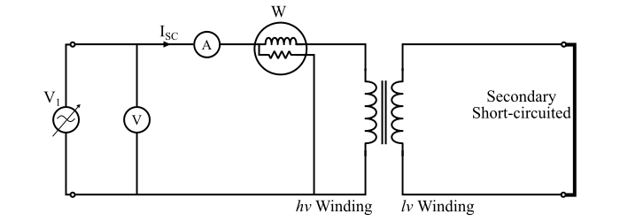
Now, the high voltage winding is supplied at the reduced voltage from a variable voltage source. The low-supply voltage is gradually increased until rated full-load primary current flows. When the rated full-load current flows in the primary winding, then the secondary winding also has full-load current by the transformer action.
Under such condition, the ammeter reading is I1SC which is equal to the full-load primary current. The voltmeter reading is V1SC which is the value of applied voltage to the primary winding when the full-load currents are flowing in the primary and secondary windings. As the applied voltage is very low (about 5 to 10 % of the rated primary voltage) so the magnetic flux (φm) produced by it is also low.
Since the iron losses are proportional to the square of the magnetic flux (φm), the iron losses are so small that they can be neglected. Although, the windings are carrying rated full load currents and no output being taken from the transformer under short-circuit condition. Hence, the whole input power to the transformer is used in supplying the full-load copper losses.
Hence, the wattmeter reading will practically give to the full-load copper losses in the windings of the transformer.
The readings of the instruments which are connected in the circuit of the short-circuit test are as follows −
$$\mathrm{\text{Ammeter reading }\:= \: \text{ Full load primary current} \:(I_{1SC})}$$
$$\mathrm{\text{Voltmeter reading}\: = \text{ Short circuit voltage } \:(V_{1sc})}$$
$$\mathrm{\text{Wattmeter reading }\:= \: \text{ Full load cu loss } \:(P_{cufl})}$$
Following calculations can be made using these readings of the instruments −
- Full-load copper loss in the transformer −
$$\mathrm{P_{cufl} \: = \: V_{1sc}I_{1sc} \: \cos \: \phi_{sc}}$$
- Short-circuit power factor −
$$\mathrm{\cos \: \phi_{sc} \: = \: \frac{P_{cufl}}{V_{1sc} I_{1sc}}}$$
- Total resistance of transformer referred to primary side −
$$\mathrm{R_{01} \: = \: \frac{P_{cufl}}{{I^{2}_{1sc}}}}$$
- Total impedance of transformer referred to primary side −
$$\mathrm{Z_{01} \: = \: \frac{V_{1sc}}{I_{1sc}}}$$
- Total reactance of transformer referred to primary side −
$$\mathrm{X_{01} \: = \: \sqrt{{Z^{2}_{01}} \: - \: {R^{2}_{01}}}}$$
Important − The short-circuit test is always performed on high-voltage side i.e. the low voltage winding is always short-circuited. If the test is performed on the low-voltage winding, then, the high voltage winding being short-circuited and hence, the voltage will be inconveniently low and the current would be inconveniently high.