- Electrical Machines - Home
- Basic Concepts
- Electromechanical Energy Conversion
- Energy Stored in Magnetic Field
- Singly-Excited and Doubly Excited Systems
- Rotating Electrical Machines
- Electrical Machines Types
- Faraday’s Laws of Electromagnetic Induction
- Concept of Induced EMF
- Fleming's Left Hand and Right Hand Rules
- Transformers
- Electrical Transformer
- Construction of Transformer
- EMF Equation of Transformer
- Turns Ratio and Voltage Transformation Ratio
- Ideal Transformer
- Practical Transformer
- Ideal and Practical Transformers
- Transformer on DC
- Losses in a Transformer
- Efficiency of Transformer
- 3-Phase Transformer
- Types of Transformers
- More on Transformers
- Transformer Working Principle
- Single-Phase Transformer Working Principle
- 3-Phase Transformer Principle
- 3-Phase Induction Motor Torque-Slip
- 3-Phase Induction Motor Torque-Speed
- 3-Phase Transformer Harmonics
- Double-Star Connection (3-6 Phase)
- Double-delta Connection (3-6 Phase)
- Transformer Ratios
- Voltage Regulation
- Delta-Star Connection (3-Phase)
- Star-Delta Connection (3-Phase)
- Autotransformer Conversion
- Back-to-back Test (Sumpner's Test)
- Transformer Voltage Drop
- Autotransformer Output
- Open and Short Circuit Test
- 3-Phase Autotransformer
- Star-Star Connection
- 6-Phase Diametrical Connections
- Circuit Test (Three-Winding)
- Potential Transformer
- Transformers Parallel Operation
- Open Delta (V-V) Connection
- Autotransformer
- Current Transformer
- No-Load Current Wave
- Transformer Inrush Current
- Transformer Vector Groups
- 3 to 12-Phase Transformers
- Scott-T Transformer Connection
- Transformer kVA Rating
- Three-Winding Transformer
- Delta-Delta Connection Transformer
- Transformer DC Supply Issue
- Equivalent Circuit Transformer
- Simplified Equivalent Circuit of Transformer
- Transformer No-Load Condition
- Transformer Load Condition
- OTI WTI Transformer
- CVT Transformer
- Isolation vs Regular Transformer
- Dry vs Oil-Filled
- DC Machines
- Construction of DC Machines
- Types of DC Machines
- Working Principle of DC Generator
- EMF Equation of DC Generator
- Derivation of EMF Equation DC Generator
- Types of DC Generators
- Working Principle of DC Motor
- Back EMF in DC Motor
- Types of DC Motors
- Losses in DC Machines
- Applications of DC Machines
- More on DC Machines
- DC Generator
- DC Generator Armature Reaction
- DC Generator Commutator Action
- Stepper vs DC Motors
- DC Shunt Generators Critical Resistance
- DC Machines Commutation
- DC Motor Characteristics
- Synchronous Generator Working Principle
- DC Generator Characteristics
- DC Generator Demagnetizing & Cross-Magnetizing
- DC Motor Voltage & Power Equations
- DC Generator Efficiency
- Electric Breaking of DC Motors
- DC Motor Efficiency
- Four Quadrant Operation of DC Motors
- Open Circuit Characteristics of DC Generators
- Voltage Build-Up in Self-Excited DC Generators
- Types of Armature Winding in DC Machines
- Torque in DC Motors
- Swinburne’s Test of DC Machine
- Speed Control of DC Shunt Motor
- Speed Control of DC Series Motor
- DC Motor of Speed Regulation
- Hopkinson's Test
- Permanent Magnet DC Motor
- Permanent Magnet Stepper Motor
- DC Servo Motor Theory
- DC Series vs Shunt Motor
- BLDC Motor vs PMSM Motor
- Induction Motors
- Introduction to Induction Motor
- Single-Phase Induction Motor
- 3-Phase Induction Motor
- Construction of 3-Phase Induction Motor
- 3-Phase Induction Motor on Load
- Characteristics of 3-Phase Induction Motor
- Speed Regulation and Speed Control
- Methods of Starting 3-Phase Induction Motors
- More on Induction Motors
- 3-Phase Induction Motor Working Principle
- 3-Phase Induction Motor Rotor Parameters
- Double Cage Induction Motor Equivalent Circuit
- Induction Motor Equivalent Circuit Models
- Slip Ring vs Squirrel Cage Induction Motors
- Single-Cage vs Double-Cage Induction Motor
- Induction Motor Equivalent Circuits
- Induction Motor Crawling & Cogging
- Induction Motor Blocked Rotor Test
- Induction Motor Circle Diagram
- 3-Phase Induction Motors Applications
- 3-Phase Induction Motors Torque Ratios
- Induction Motors Power Flow Diagram & Losses
- Determining Induction Motor Efficiency
- Induction Motor Speed Control by Pole-Amplitude Modulation
- Induction Motor Inverted or Rotor Fed
- High Torque Cage Motors
- Double-Cage Induction Motor Torque-Slip Characteristics
- 3-Phase Induction Motors Starting Torque
- 3-phase Induction Motor - Rotor Resistance Starter
- 3-phase Induction Motor Running Torque
- 3-Phase Induction Motor - Rotating Magnetic Field
- Isolated Induction Generator
- Capacitor-Start Induction Motor
- Capacitor-Start Capacitor-Run Induction Motor
- Winding EMFs in 3-Phase Induction Motors
- Split-Phase Induction Motor
- Shaded Pole Induction Motor
- Repulsion-Start Induction-Run Motor
- Repulsion Induction Motor
- PSC Induction Motor
- Single-Phase Induction Motor Performance Analysis
- Linear Induction Motor
- Single-Phase Induction Motor Testing
- 3-Phase Induction Motor Fault Types
- Synchronous Machines
- Introduction to 3-Phase Synchronous Machines
- Construction of Synchronous Machine
- Working of 3-Phase Alternator
- Armature Reaction in Synchronous Machines
- Output Power of 3-Phase Alternator
- Losses and Efficiency of an Alternator
- Losses and Efficiency of 3-Phase Alternator
- Working of 3-Phase Synchronous Motor
- Equivalent Circuit and Power Factor of Synchronous Motor
- Power Developed by Synchronous Motor
- More on Synchronous Machines
- AC Motor Types
- Induction Generator (Asynchronous Generator)
- Synchronous Speed Slip of 3-Phase Induction Motor
- Armature Reaction in Alternator at Leading Power Factor
- Armature Reaction in Alternator at Lagging Power Factor
- Stationary Armature vs Rotating Field Alternator Advantages
- Synchronous Impedance Method for Voltage Regulation
- Saturated & Unsaturated Synchronous Reactance
- Synchronous Reactance & Impedance
- Significance of Short Circuit Ratio in Alternator
- Hunting Effect Alternator
- Hydrogen Cooling in Synchronous Generators
- Excitation System of Synchronous Machine
- Equivalent Circuit Phasor Diagram of Synchronous Generator
- EMF Equation of Synchronous Generator
- Cooling Methods for Synchronous Generators
- Assumptions in Synchronous Impedance Method
- Armature Reaction at Unity Power Factor
- Voltage Regulation of Alternator
- Synchronous Generator with Infinite Bus Operation
- Zero Power Factor of Synchronous Generator
- Short Circuit Ratio Calculation of Synchronous Machines
- Speed-Frequency Relationship in Alternator
- Pitch Factor in Alternator
- Max Reactive Power in Synchronous Generators
- Power Flow Equations for Synchronous Generator
- Potier Triangle for Voltage Regulation in Alternators
- Parallel Operation of Alternators
- Load Sharing in Parallel Alternators
- Slip Test on Synchronous Machine
- Constant Flux Linkage Theorem
- Blondel's Two Reaction Theory
- Synchronous Machine Oscillations
- Ampere Turn Method for Voltage Regulation
- Salient Pole Synchronous Machine Theory
- Synchronization by Synchroscope
- Synchronization by Synchronizing Lamp Method
- Sudden Short Circuit in 3-Phase Alternator
- Short Circuit Transient in Synchronous Machines
- Power-Angle of Salient Pole Machines
- Prime-Mover Governor Characteristics
- Power Input of Synchronous Generator
- Power Output of Synchronous Generator
- Power Developed by Salient Pole Motor
- Phasor Diagrams of Cylindrical Rotor Moto
- Synchronous Motor Excitation Voltage Determination
- Hunting Synchronous Motor
- Self-Starting Synchronous Motor
- Unidirectional Torque Production in Synchronous Motor
- Effect of Load Change on Synchronous Motor
- Field Excitation Effect on Synchronous Motor
- Output Power of Synchronous Motor
- Input Power of Synchronous Motor
- V Curves & Inverted V Curves of Synchronous Motor
- Torque in Synchronous Motor
- Construction of 3-Phase Synchronous Motor
- Synchronous Motor
- Synchronous Condenser
- Power Flow in Synchronous Motor
- Types of Faults in Alternator
- Miscellaneous Topics
- Electrical Generator
- Determining Electric Motor Load
- Solid State Motor Starters
- Characteristics of Single-Phase Motor
- Types of AC Generators
- Three-Point Starter
- Four-Point Starter
- Ward Leonard Speed Control Method
- Pole Changing Method
- Stator Voltage Control Method
- DOL Starter
- Star-Delta Starter
- Hysteresis Motor
- 2-Phase & 3-Phase AC Servo Motors
- Repulsion Motor
- Reluctance Motor
- Stepper Motor
- PCB Motor
- Single-Stack Variable Reluctance Stepper Motor
- Schrage Motor
- Hybrid Schrage Motor
- Multi-Stack Variable Reluctance Stepper Motor
- Universal Motor
- Step Angle in Stepper Motor
- Stepper Motor Torque-Pulse Rate Characteristics
- Distribution Factor
- Electrical Machines Basic Terms
- Synchronizing Torque Coefficient
- Synchronizing Power Coefficient
- Metadyne
- Motor Soft Starter
- CVT vs PT
- Metering CT vs Protection CT
- Stator and Rotor in Electrical Machines
- Electric Motor Winding
- Electric Motor
- Useful Resources
- Quick Guide
- Resources
- Discussion
Difference Between Isolation Transformer and Regular Transformer
An electrical transformer is one of the most widely used electrical machines in power system. The main function of a transformer is to change the voltage levels in the system for different purposes. Depending on the purpose, these transformers can be classified into different types like step-up transformer, step-down transformer, or isolation transformer.
The step-up or step-down transformers can also be referred to as regular transformers. These are used for changing the level of supply voltage. On the other hand, an isolation transformer is used for providing an electrical separation between the input and output circuits.
The most fundamental difference between an isolation transformer and a regular transformer is that an isolation transformer is used for providing electrical isolation/separation between input and output circuits while a regular transformer is used for changing the voltage levels in the system.
In this article, we will explain all the important differences between regular transformers and isolation transformers along with their basics, purposes, and advantages. So, lets start with the basics of a regular transformer.
What is a Regular Transformer?
A regular transformer, normally referred to as an electrical transformer or just transformer, is an electrical machine used for transferring electrical energy from one circuit to another through electromagnetic induction with a change in supply voltage. Therefore, a regular transformer is used for either increasing or decreasing the supply voltage to meet the requirements of the load connected.
These transformers can be classified into two types namely, step-down transformer and step-up transformer as shown in the following figure.
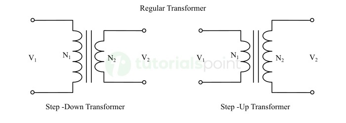
For a step-down transformer,
$$\mathrm{V_{1} \: \gt \:V_{2}}$$
$$\mathrm{N_{1} \: \gt \:N_{2}}$$
For a step-up transformer,
$$\mathrm{V_{1}\:\lt \:V_{2}}$$
$$\mathrm{N_{1}\:\lt \:N_{2}}$$
Where, V1 is the input voltage, V2 is the output voltage, N1 is the primary winding turns, and N2 is the secondary winding turns.
Regular transformers are extensively used in generating stations, transmission systems, and distribution systems for supplying electrical power to the end consumers.
What is an Isolation Transformer?
An isolation transformer is simply an electrical transformer which is used for providing electrical separation between the input and output circuits of the electrical system. This transformer typically has equal number turns in both primary and secondary windings i.e.,
$$\mathrm{N_1 \: = \: N_2}$$
Therefore, the primary and secondary voltages are also equal i.e.,
$$\mathrm{V_1 \: = \: V_2}$$

Electrical separation is provided in electrical systems for protecting them from unwanted power surges, transients, and noise and improve the reliability and efficiency of the system.
An isolation transformer separates the input and output circuits electrically, but it couples them magnetically. Since an isolation transformer has the same number of primary and secondary winding turns, it is also called as a 1:1 transformer. In this type of electrical transformer, a high-grade insulation material is used for providing effective electrical isolation between the primary and secondary windings.
Isolation transformers are primarily used in sensitive electrical systems like telecommunication systems, medical equipment, industrial control systems, etc.
Difference Between Regular Transformer and Isolation Transformer
The following table highlights all the significant differences between regular transformer and isolation transformer
| Parameter | Regular Transformer | Isolation Transformer |
|---|---|---|
| Purpose | A regular transformer is used for changing (increasing or decreasing) the voltage levels in a system. | An isolation transformer is used for providing electrical isolation between input and output circuits. |
| Types | A regular transformer can be of two types namely, step-up or step-down. | There is no such classification of isolation transformer. |
| Design consideration | A regular transformer is designed for effective voltage transformation without much concerning about isolation. | Isolation transformers are designed to have a high degree of electrical isolation between primary and secondary windings. |
| Number of turns | A regular transformer can have either $\mathrm{N_1\:\gt \:N_2\:or\:N_1\:\lt \:N_2.}$ | An isolation transformer typically has an equal number of turns in both windings i.e., $\mathrm{N_1\:=\:N_2.}$ |
| Input and output voltages | A regular transformer can have voltages as $\mathrm{V_1\:\lt \:V_2\:or\:V_1\:\gt \:V_2.}$ | An isolation transformer typically has voltages as $\mathrm{V_1\:=\:V_2.}$ |
| Power rating | Regular transformers can have any power rating depending on the requirements of the application. | Isolation transformers generally have small power ratings. |
| Shielding against EMI | Regular transformers are not effective in reducing the electromagnetic interference. | Isolation transformers are designed to provide protection against electromagnetic interference. |
| Physical size | The size of a regular transformer depends on its power rating. | Isolation transformers usually have a smaller physical size. |
| Suppression of harmonics | Regular transformers usually do not have harmonics suppression capabilities. | Isolation transformers can reduce harmonics effectively. |
| Efficiency | Regular transformers are less efficient. | Isolation transformers are more efficient than regular transformers. |
| Energy loss inside the transformer | Regular transformers have more energy loss inside them. | Isolation transformers have lower energy losses inside them. |
| Initial cost | Regular transformers are less expensive to purchase. | Isolation transformers are more expensive due to specialized design. |
| Operational cost | Regular transformers have high operational cost due to lower efficiency. | Isolation transformers have low operational cost. |
| Applications | Regular transformers are commonly used in power systems for transmission and distribution of electrical power at different voltage levels. | Isolation transformers are used in telecommunication systems, medical equipment, industrial automation, etc. for providing electrical isolation. |
Conclusion
From the above comparison, we can conclude that the operating principle of both transformers is the same i.e., electromagnetic induction. But an isolation transformer is specially designed to provide complete electrical separation between input and output circuits, while a regular transformer is designed for voltage transformation.