- Electrical Machines - Home
- Basic Concepts
- Electromechanical Energy Conversion
- Energy Stored in Magnetic Field
- Singly-Excited and Doubly Excited Systems
- Rotating Electrical Machines
- Electrical Machines Types
- Faraday’s Laws of Electromagnetic Induction
- Concept of Induced EMF
- Fleming's Left Hand and Right Hand Rules
- Transformers
- Electrical Transformer
- Construction of Transformer
- EMF Equation of Transformer
- Turns Ratio and Voltage Transformation Ratio
- Ideal Transformer
- Practical Transformer
- Ideal and Practical Transformers
- Transformer on DC
- Losses in a Transformer
- Efficiency of Transformer
- 3-Phase Transformer
- Types of Transformers
- More on Transformers
- Transformer Working Principle
- Single-Phase Transformer Working Principle
- 3-Phase Transformer Principle
- 3-Phase Induction Motor Torque-Slip
- 3-Phase Induction Motor Torque-Speed
- 3-Phase Transformer Harmonics
- Double-Star Connection (3-6 Phase)
- Double-delta Connection (3-6 Phase)
- Transformer Ratios
- Voltage Regulation
- Delta-Star Connection (3-Phase)
- Star-Delta Connection (3-Phase)
- Autotransformer Conversion
- Back-to-back Test (Sumpner's Test)
- Transformer Voltage Drop
- Autotransformer Output
- Open and Short Circuit Test
- 3-Phase Autotransformer
- Star-Star Connection
- 6-Phase Diametrical Connections
- Circuit Test (Three-Winding)
- Potential Transformer
- Transformers Parallel Operation
- Open Delta (V-V) Connection
- Autotransformer
- Current Transformer
- No-Load Current Wave
- Transformer Inrush Current
- Transformer Vector Groups
- 3 to 12-Phase Transformers
- Scott-T Transformer Connection
- Transformer kVA Rating
- Three-Winding Transformer
- Delta-Delta Connection Transformer
- Transformer DC Supply Issue
- Equivalent Circuit Transformer
- Simplified Equivalent Circuit of Transformer
- Transformer No-Load Condition
- Transformer Load Condition
- OTI WTI Transformer
- CVT Transformer
- Isolation vs Regular Transformer
- Dry vs Oil-Filled
- DC Machines
- Construction of DC Machines
- Types of DC Machines
- Working Principle of DC Generator
- EMF Equation of DC Generator
- Derivation of EMF Equation DC Generator
- Types of DC Generators
- Working Principle of DC Motor
- Back EMF in DC Motor
- Types of DC Motors
- Losses in DC Machines
- Applications of DC Machines
- More on DC Machines
- DC Generator
- DC Generator Armature Reaction
- DC Generator Commutator Action
- Stepper vs DC Motors
- DC Shunt Generators Critical Resistance
- DC Machines Commutation
- DC Motor Characteristics
- Synchronous Generator Working Principle
- DC Generator Characteristics
- DC Generator Demagnetizing & Cross-Magnetizing
- DC Motor Voltage & Power Equations
- DC Generator Efficiency
- Electric Breaking of DC Motors
- DC Motor Efficiency
- Four Quadrant Operation of DC Motors
- Open Circuit Characteristics of DC Generators
- Voltage Build-Up in Self-Excited DC Generators
- Types of Armature Winding in DC Machines
- Torque in DC Motors
- Swinburne’s Test of DC Machine
- Speed Control of DC Shunt Motor
- Speed Control of DC Series Motor
- DC Motor of Speed Regulation
- Hopkinson's Test
- Permanent Magnet DC Motor
- Permanent Magnet Stepper Motor
- DC Servo Motor Theory
- DC Series vs Shunt Motor
- BLDC Motor vs PMSM Motor
- Induction Motors
- Introduction to Induction Motor
- Single-Phase Induction Motor
- 3-Phase Induction Motor
- Construction of 3-Phase Induction Motor
- 3-Phase Induction Motor on Load
- Characteristics of 3-Phase Induction Motor
- Speed Regulation and Speed Control
- Methods of Starting 3-Phase Induction Motors
- More on Induction Motors
- 3-Phase Induction Motor Working Principle
- 3-Phase Induction Motor Rotor Parameters
- Double Cage Induction Motor Equivalent Circuit
- Induction Motor Equivalent Circuit Models
- Slip Ring vs Squirrel Cage Induction Motors
- Single-Cage vs Double-Cage Induction Motor
- Induction Motor Equivalent Circuits
- Induction Motor Crawling & Cogging
- Induction Motor Blocked Rotor Test
- Induction Motor Circle Diagram
- 3-Phase Induction Motors Applications
- 3-Phase Induction Motors Torque Ratios
- Induction Motors Power Flow Diagram & Losses
- Determining Induction Motor Efficiency
- Induction Motor Speed Control by Pole-Amplitude Modulation
- Induction Motor Inverted or Rotor Fed
- High Torque Cage Motors
- Double-Cage Induction Motor Torque-Slip Characteristics
- 3-Phase Induction Motors Starting Torque
- 3-phase Induction Motor - Rotor Resistance Starter
- 3-phase Induction Motor Running Torque
- 3-Phase Induction Motor - Rotating Magnetic Field
- Isolated Induction Generator
- Capacitor-Start Induction Motor
- Capacitor-Start Capacitor-Run Induction Motor
- Winding EMFs in 3-Phase Induction Motors
- Split-Phase Induction Motor
- Shaded Pole Induction Motor
- Repulsion-Start Induction-Run Motor
- Repulsion Induction Motor
- PSC Induction Motor
- Single-Phase Induction Motor Performance Analysis
- Linear Induction Motor
- Single-Phase Induction Motor Testing
- 3-Phase Induction Motor Fault Types
- Synchronous Machines
- Introduction to 3-Phase Synchronous Machines
- Construction of Synchronous Machine
- Working of 3-Phase Alternator
- Armature Reaction in Synchronous Machines
- Output Power of 3-Phase Alternator
- Losses and Efficiency of an Alternator
- Losses and Efficiency of 3-Phase Alternator
- Working of 3-Phase Synchronous Motor
- Equivalent Circuit and Power Factor of Synchronous Motor
- Power Developed by Synchronous Motor
- More on Synchronous Machines
- AC Motor Types
- Induction Generator (Asynchronous Generator)
- Synchronous Speed Slip of 3-Phase Induction Motor
- Armature Reaction in Alternator at Leading Power Factor
- Armature Reaction in Alternator at Lagging Power Factor
- Stationary Armature vs Rotating Field Alternator Advantages
- Synchronous Impedance Method for Voltage Regulation
- Saturated & Unsaturated Synchronous Reactance
- Synchronous Reactance & Impedance
- Significance of Short Circuit Ratio in Alternator
- Hunting Effect Alternator
- Hydrogen Cooling in Synchronous Generators
- Excitation System of Synchronous Machine
- Equivalent Circuit Phasor Diagram of Synchronous Generator
- EMF Equation of Synchronous Generator
- Cooling Methods for Synchronous Generators
- Assumptions in Synchronous Impedance Method
- Armature Reaction at Unity Power Factor
- Voltage Regulation of Alternator
- Synchronous Generator with Infinite Bus Operation
- Zero Power Factor of Synchronous Generator
- Short Circuit Ratio Calculation of Synchronous Machines
- Speed-Frequency Relationship in Alternator
- Pitch Factor in Alternator
- Max Reactive Power in Synchronous Generators
- Power Flow Equations for Synchronous Generator
- Potier Triangle for Voltage Regulation in Alternators
- Parallel Operation of Alternators
- Load Sharing in Parallel Alternators
- Slip Test on Synchronous Machine
- Constant Flux Linkage Theorem
- Blondel's Two Reaction Theory
- Synchronous Machine Oscillations
- Ampere Turn Method for Voltage Regulation
- Salient Pole Synchronous Machine Theory
- Synchronization by Synchroscope
- Synchronization by Synchronizing Lamp Method
- Sudden Short Circuit in 3-Phase Alternator
- Short Circuit Transient in Synchronous Machines
- Power-Angle of Salient Pole Machines
- Prime-Mover Governor Characteristics
- Power Input of Synchronous Generator
- Power Output of Synchronous Generator
- Power Developed by Salient Pole Motor
- Phasor Diagrams of Cylindrical Rotor Moto
- Synchronous Motor Excitation Voltage Determination
- Hunting Synchronous Motor
- Self-Starting Synchronous Motor
- Unidirectional Torque Production in Synchronous Motor
- Effect of Load Change on Synchronous Motor
- Field Excitation Effect on Synchronous Motor
- Output Power of Synchronous Motor
- Input Power of Synchronous Motor
- V Curves & Inverted V Curves of Synchronous Motor
- Torque in Synchronous Motor
- Construction of 3-Phase Synchronous Motor
- Synchronous Motor
- Synchronous Condenser
- Power Flow in Synchronous Motor
- Types of Faults in Alternator
- Miscellaneous Topics
- Electrical Generator
- Determining Electric Motor Load
- Solid State Motor Starters
- Characteristics of Single-Phase Motor
- Types of AC Generators
- Three-Point Starter
- Four-Point Starter
- Ward Leonard Speed Control Method
- Pole Changing Method
- Stator Voltage Control Method
- DOL Starter
- Star-Delta Starter
- Hysteresis Motor
- 2-Phase & 3-Phase AC Servo Motors
- Repulsion Motor
- Reluctance Motor
- Stepper Motor
- PCB Motor
- Single-Stack Variable Reluctance Stepper Motor
- Schrage Motor
- Hybrid Schrage Motor
- Multi-Stack Variable Reluctance Stepper Motor
- Universal Motor
- Step Angle in Stepper Motor
- Stepper Motor Torque-Pulse Rate Characteristics
- Distribution Factor
- Electrical Machines Basic Terms
- Synchronizing Torque Coefficient
- Synchronizing Power Coefficient
- Metadyne
- Motor Soft Starter
- CVT vs PT
- Metering CT vs Protection CT
- Stator and Rotor in Electrical Machines
- Electric Motor Winding
- Electric Motor
- Useful Resources
- Quick Guide
- Resources
- Discussion
What is Electric Motor?
Electric motor is a most widely used electrical machine in a wide range of applications from domestic to industrial. It is a type of electromechanical energy conversion device that transforms electrical energy into mechanical energy. The principle of electromechanical energy conversion was given by Michael Faraday in 1821.
This article is meant for explaining the basics of electric motor, such as definition, construction, working, types, etc. So, lets get started with the basic introduction to electric motor.
What is an Electric Motor?
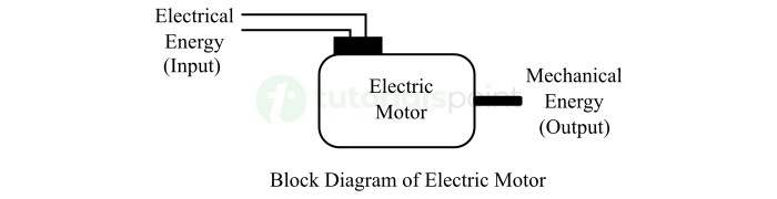
An electromechanical energy conversion device that transforms electrical energy into mechanical energy is called an electric motor.
Therefore, an electric motor takes electricity as the input and produces mechanical energy in the form of rotation of shaft as the output.
The block diagram of an electric motor is depicted in the following figure.
An electric motor is one of simplest mean for producing mechanical power from electrical power.
Electric motors are commonly used to drive mechanical loads like fans, pumps, compressors, conveyors, lifts, cranes, air conditioners, and more.
Construction of Electric Motor
In actual practice, we have different types of electric motors having different constructions. But all the electric motors have the same fundamental structure.
A typical electric motor has two essential parts namely, stator and rotor.
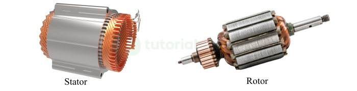
The stator is a stationary or non-moving part of the motor. While, the rotor is a moving or rotating part of the motor.
The stator has a winding called stator winding. The stator also provides the mechanical covering and protection against mechanical threats to the internal parts of the motor. The stator of an electric motor is basically a hollow cylinder made up of cast iron.
The rotor of the electric motor is a moving part having a rotor core, rotor winding, and a mechanical shaft. The rotor core is a cylindrical piece of steel provides housing to the rotor winding. The rotor core is mounted on the shaft and a mechanical load is attached to the motor shaft.
Apart from stator and rotor, an electric motor also has some auxiliary parts such as bearings to reduce friction between moving and stationary parts, cooling fans to balance the temperature of the motor, etc.
Let us now understand how does an electric motor work.
Working of Electric Motor
An electric motor works on the principle of electromechanical energy conversion through electromagnetic induction.
In an electric motor, there are two windings namely, field winding and armature winding. The placement of these windings depends on type of design of the motor. For example, in an induction motor the field winding is placed on stator, while in a synchronous motor, the field winding is placed on the rotor. But the functions of these two windings remain the same in all types of motors.
The field winding produces the working magnetic flux in the motor while the armature winding develops the torque required to drive the mechanical load connected to the shaft.
When electrical energy is input to the electric motor, a magnetic field is produced in the air gap between the stator and rotor. This magnetic field cuts the armature winding and induces an emf and a current in the armature winding through the electromagnetic induction. Due to current in the armature winding, a magnetic flux is produced.
Now, there are two magnetic fields inside the motor namely, main field and armature field. These two magnetic fields interact with each other and produces a torque that rotates the rotor.
This is how an electric motor works when an electrical input is given to it.
Classification of Electric Motors
Electric motors are broadly classified into the following two types
DC Motor
An electric motor that takes direct current electricity to work and produce mechanical energy output is called a DC motor or direct current motor.
AC Motor
An electric motor that requires alternating current electric supply to operate and produce mechanical energy output is called an AC motor or alternating current motor.
Types of Electric Motors
Based on power supply, electric motors can be classified into the following two types
- DC Motor (Direct Current Motor)
- AC Motor (Alternating Current Motor)
The dc motors are further classified into the following major types
- Permanent Magnet DC Motor
- Separately Excited DC Motor
- DC Series Motor
- DC Shunt Motor
- DC Compound Motor
The ac motors are classified into the following major types
- Single-Phase Induction Motor
- Three-Phase Induction Motor
- Synchronous Motor
There are some special types of electric motors used in practical applications, they are
- BLDC (Brushless Direct Current) Motor
- Hysteresis Motor
- Reluctance Motor
- Universal Motor
- Repulsion Motor
Let us now discuss practical applications of each of these electric motors.
Applications of Permanent Magnet DC Motor
A permanent magnet dc motor is a one which has permanent magnetic poles in its magnetic field system. This type of dc motor is used in the low power applications. Some practical applications of permanent magnet dc motors are given below
- Printers, computer memories, CPU fans, etc.
- Automobile wipers, windows, etc.
- Electronic toys.
- Portable vacuum cleaners.
- Camera lenses.
- Portable tools like trimmers, drills, etc.
Applications of Separately Excited DC Motor
A separately excited DC motor is a type of dc motor which has a field winding excited from a separate DC power supply. This type of dc motor is used in the following applications
- In electric trains and automatic traction systems.
- In actuators.
- In special industrial applications.
- Rolling machines.
- Paper machines, etc.
Applications of DC Series Motor
A dc series motor is one in which the field winding is connected in series with the armature winding. Hence, in dc series motors, the field winding carries equal current to the armature winding and thus produces a high starting torque.
DC series motors are used in applications where high starting torque and variable speed is required. Some common applications of dc series motors in practice are as follows
- Cranes and hoists
- Lifts
- Electric trains and vehicles
- Vacuum cleaners
- Hair driers
- Air compressors
- Electric hammers, etc.
Applications of DC Shunt Motor
A dc shunt motor has a field winding connected in parallel to the armature winding and receives full supply voltage. Since the voltage across shunt field winding is constant. Hence, DC shunt motors are considered constant speed motors.
The dc shunt motors are widely used in the following practical applications
- Blowers and fans
- Printers
- Centrifugal pumps
- Lathe machines
- Elevators, etc.
Applications of DC Compound Motor
A dc compound motor is one which has both series field winding and shunt field winding to produce the working magnetic field in the machine. Therefore, this type of dc motor exhibits characteristics of both dc series and shunt motors.
The dc compound motors are used in the following applications
- Rolling mills
- Electric drives used for conveyor belt
- Elevators
- Compressors
- Electric presses, etc.
Applications of 1-Phase Induction Motor
Single-phase induction motor is a type of alternating current motor that works on single-phase ac supply. These motors are designed to operate light loads used in domestic, commercial, or industrial applications. Some examples of practical applications of single-phase induction motor are listed below
- Pumps
- Fans and coolers
- Flour mills
- Compressors
- Grinders, and other low power appliances.
Applications of 3-Phase Induction Motor
A three-phase induction motor is an electric motor that requires three-phase supply to operate. It is a most widely used electric motor in industries. These motors are generally used to drive heavy loads and machinery.
A list of some common practical applications of three-phase induction motors is given below
- Large pumps
- Large compressors, fans, blowers, etc.
- Crushers
- Rolling mills
- Large flour mills
- Textile mills
- Paper mills
- Modern electric trains and vehicles
- Lifts and cranes
- Heavy industrial machinery, etc.
Applications of Synchronous Motor
Synchronous motor is a type of alternating current motor that runs at a constant speed called synchronous speed. The speed of a synchronous motor always remains independent of the load condition on the shaft.
Synchronous motors are widely used in the following applications
- Drive heavy mechanical loads at constant speeds.
- To drive ball mills, rod mills, in industries.
- In paper mills and cement mills.
- In power plant to improve power factor, etc.
Applications of BLDC Motor
BLDC (Brushless Direct Current) motor is a specially designed dc motor does not have carbon brushes to make connection between moving and stationary components. Since these motors have brushless construction, hence they require less frequent maintenance.
The BLDC motors are commonly used in the following practical applications
- Modern fans
- Electric vehicles
- Power steering of vehicles
- Lab equipment
- Robotics and automation systems
- Hard disk drives
- Medical surgical tools, etc.
Applications of Hysteresis Motor
Hysteresis motor is a special type of synchronous motor which utilizes the hysteresis phenomenon to operate. It is basically a type of synchronous motor. It provides a silent and constant speed operation.
Some practical applications of hysteresis motors are given below
- Sound recording and producing devices
- Timing devices
- Compressors and pumps
- Electric clocks
- Tape printers
- Indicating instruments, etc.
Applications of Reluctance Motor
Reluctance motor is a special electric motor which operates on the principle of magnetic reluctance. It consists of a salient pole rotor and a stator similar to the induction motor. In the reluctance motor, the torque is produced in the rotor due to reluctance i.e., the rotor tends to align itself in the position of minimum reluctance.
The following are some common applications of reluctance motors
- Electric vehicles
- Signaling and control equipment
- Electric clocks
- Recording instruments
- Teleprinters and gramophones
- Drill or lathe machines, etc.
Applications of Universal Motor
A specially design electric motor that can run on both AC and DC power supply is called a universal motor. It is also known as AC series motor as it has a field winding connected in series with the armature winding and commonly operates on AC supply.
Universal motors are used in applications where high starting torque is required. Some common applications of universal motors are given below
- Table fans
- Hair driers
- Mixer and grinders
- Portable power tools like drill machine, grinders, etc.
- Various electric appliances used in kitchen
- Blowers, etc.
Applications of Repulsion Motor
Repulsion motor is a type of ac motor which operates on the principle of repulsion between two magnetic fields of stator and rotor. It is a type of single-phase ac motor that provides a significantly high starting torque and good operating characteristics.
Reluctance motors are commonly used in the following applications
- High speed lifts and hoists
- Toys
- Coil winders
- Electric locomotives and vehicles
- Pumps
- Fans
- Machinery used in textile industries
- Printing presses, etc.
Advantages of Electric Motors
Electric motors offer several advantages over other methods of producing mechanical energy to drive mechanical loads. Some key benefits of using electric motors are given below
- Initial and operation costs of electric motors are low.
- Electric motors have relatively longer lifespan.
- Electric motors require less maintenance.
- Electric motors provide easy start and stop and efficient speed control.
- Electric motors have less noisy operation.
- The energy conversion efficiency of electric motors is relatively high.
Conclusion
In conclusion, electric motor is an essential electrical machine used to convert electrical energy into mechanical energy. A typical electric motor consists of two major parts namely stator and rotor. The working of an electric motor is based on the principle of electromechanical energy conversion through the electromagnetic induction. Electric motors are widely used in various applications like in fans, refrigerators, conveyors, crushers, electric vehicles, and more. In this detailed article on electric motor, I have explained the definition, construction, and working of electric motor.