- Electrical Machines - Home
- Basic Concepts
- Electromechanical Energy Conversion
- Energy Stored in Magnetic Field
- Singly-Excited and Doubly Excited Systems
- Rotating Electrical Machines
- Electrical Machines Types
- Faraday’s Laws of Electromagnetic Induction
- Concept of Induced EMF
- Fleming's Left Hand and Right Hand Rules
- Transformers
- Electrical Transformer
- Construction of Transformer
- EMF Equation of Transformer
- Turns Ratio and Voltage Transformation Ratio
- Ideal Transformer
- Practical Transformer
- Ideal and Practical Transformers
- Transformer on DC
- Losses in a Transformer
- Efficiency of Transformer
- 3-Phase Transformer
- Types of Transformers
- More on Transformers
- Transformer Working Principle
- Single-Phase Transformer Working Principle
- 3-Phase Transformer Principle
- 3-Phase Induction Motor Torque-Slip
- 3-Phase Induction Motor Torque-Speed
- 3-Phase Transformer Harmonics
- Double-Star Connection (3-6 Phase)
- Double-delta Connection (3-6 Phase)
- Transformer Ratios
- Voltage Regulation
- Delta-Star Connection (3-Phase)
- Star-Delta Connection (3-Phase)
- Autotransformer Conversion
- Back-to-back Test (Sumpner's Test)
- Transformer Voltage Drop
- Autotransformer Output
- Open and Short Circuit Test
- 3-Phase Autotransformer
- Star-Star Connection
- 6-Phase Diametrical Connections
- Circuit Test (Three-Winding)
- Potential Transformer
- Transformers Parallel Operation
- Open Delta (V-V) Connection
- Autotransformer
- Current Transformer
- No-Load Current Wave
- Transformer Inrush Current
- Transformer Vector Groups
- 3 to 12-Phase Transformers
- Scott-T Transformer Connection
- Transformer kVA Rating
- Three-Winding Transformer
- Delta-Delta Connection Transformer
- Transformer DC Supply Issue
- Equivalent Circuit Transformer
- Simplified Equivalent Circuit of Transformer
- Transformer No-Load Condition
- Transformer Load Condition
- OTI WTI Transformer
- CVT Transformer
- Isolation vs Regular Transformer
- Dry vs Oil-Filled
- DC Machines
- Construction of DC Machines
- Types of DC Machines
- Working Principle of DC Generator
- EMF Equation of DC Generator
- Derivation of EMF Equation DC Generator
- Types of DC Generators
- Working Principle of DC Motor
- Back EMF in DC Motor
- Types of DC Motors
- Losses in DC Machines
- Applications of DC Machines
- More on DC Machines
- DC Generator
- DC Generator Armature Reaction
- DC Generator Commutator Action
- Stepper vs DC Motors
- DC Shunt Generators Critical Resistance
- DC Machines Commutation
- DC Motor Characteristics
- Synchronous Generator Working Principle
- DC Generator Characteristics
- DC Generator Demagnetizing & Cross-Magnetizing
- DC Motor Voltage & Power Equations
- DC Generator Efficiency
- Electric Breaking of DC Motors
- DC Motor Efficiency
- Four Quadrant Operation of DC Motors
- Open Circuit Characteristics of DC Generators
- Voltage Build-Up in Self-Excited DC Generators
- Types of Armature Winding in DC Machines
- Torque in DC Motors
- Swinburne’s Test of DC Machine
- Speed Control of DC Shunt Motor
- Speed Control of DC Series Motor
- DC Motor of Speed Regulation
- Hopkinson's Test
- Permanent Magnet DC Motor
- Permanent Magnet Stepper Motor
- DC Servo Motor Theory
- DC Series vs Shunt Motor
- BLDC Motor vs PMSM Motor
- Induction Motors
- Introduction to Induction Motor
- Single-Phase Induction Motor
- 3-Phase Induction Motor
- Construction of 3-Phase Induction Motor
- 3-Phase Induction Motor on Load
- Characteristics of 3-Phase Induction Motor
- Speed Regulation and Speed Control
- Methods of Starting 3-Phase Induction Motors
- More on Induction Motors
- 3-Phase Induction Motor Working Principle
- 3-Phase Induction Motor Rotor Parameters
- Double Cage Induction Motor Equivalent Circuit
- Induction Motor Equivalent Circuit Models
- Slip Ring vs Squirrel Cage Induction Motors
- Single-Cage vs Double-Cage Induction Motor
- Induction Motor Equivalent Circuits
- Induction Motor Crawling & Cogging
- Induction Motor Blocked Rotor Test
- Induction Motor Circle Diagram
- 3-Phase Induction Motors Applications
- 3-Phase Induction Motors Torque Ratios
- Induction Motors Power Flow Diagram & Losses
- Determining Induction Motor Efficiency
- Induction Motor Speed Control by Pole-Amplitude Modulation
- Induction Motor Inverted or Rotor Fed
- High Torque Cage Motors
- Double-Cage Induction Motor Torque-Slip Characteristics
- 3-Phase Induction Motors Starting Torque
- 3-phase Induction Motor - Rotor Resistance Starter
- 3-phase Induction Motor Running Torque
- 3-Phase Induction Motor - Rotating Magnetic Field
- Isolated Induction Generator
- Capacitor-Start Induction Motor
- Capacitor-Start Capacitor-Run Induction Motor
- Winding EMFs in 3-Phase Induction Motors
- Split-Phase Induction Motor
- Shaded Pole Induction Motor
- Repulsion-Start Induction-Run Motor
- Repulsion Induction Motor
- PSC Induction Motor
- Single-Phase Induction Motor Performance Analysis
- Linear Induction Motor
- Single-Phase Induction Motor Testing
- 3-Phase Induction Motor Fault Types
- Synchronous Machines
- Introduction to 3-Phase Synchronous Machines
- Construction of Synchronous Machine
- Working of 3-Phase Alternator
- Armature Reaction in Synchronous Machines
- Output Power of 3-Phase Alternator
- Losses and Efficiency of an Alternator
- Losses and Efficiency of 3-Phase Alternator
- Working of 3-Phase Synchronous Motor
- Equivalent Circuit and Power Factor of Synchronous Motor
- Power Developed by Synchronous Motor
- More on Synchronous Machines
- AC Motor Types
- Induction Generator (Asynchronous Generator)
- Synchronous Speed Slip of 3-Phase Induction Motor
- Armature Reaction in Alternator at Leading Power Factor
- Armature Reaction in Alternator at Lagging Power Factor
- Stationary Armature vs Rotating Field Alternator Advantages
- Synchronous Impedance Method for Voltage Regulation
- Saturated & Unsaturated Synchronous Reactance
- Synchronous Reactance & Impedance
- Significance of Short Circuit Ratio in Alternator
- Hunting Effect Alternator
- Hydrogen Cooling in Synchronous Generators
- Excitation System of Synchronous Machine
- Equivalent Circuit Phasor Diagram of Synchronous Generator
- EMF Equation of Synchronous Generator
- Cooling Methods for Synchronous Generators
- Assumptions in Synchronous Impedance Method
- Armature Reaction at Unity Power Factor
- Voltage Regulation of Alternator
- Synchronous Generator with Infinite Bus Operation
- Zero Power Factor of Synchronous Generator
- Short Circuit Ratio Calculation of Synchronous Machines
- Speed-Frequency Relationship in Alternator
- Pitch Factor in Alternator
- Max Reactive Power in Synchronous Generators
- Power Flow Equations for Synchronous Generator
- Potier Triangle for Voltage Regulation in Alternators
- Parallel Operation of Alternators
- Load Sharing in Parallel Alternators
- Slip Test on Synchronous Machine
- Constant Flux Linkage Theorem
- Blondel's Two Reaction Theory
- Synchronous Machine Oscillations
- Ampere Turn Method for Voltage Regulation
- Salient Pole Synchronous Machine Theory
- Synchronization by Synchroscope
- Synchronization by Synchronizing Lamp Method
- Sudden Short Circuit in 3-Phase Alternator
- Short Circuit Transient in Synchronous Machines
- Power-Angle of Salient Pole Machines
- Prime-Mover Governor Characteristics
- Power Input of Synchronous Generator
- Power Output of Synchronous Generator
- Power Developed by Salient Pole Motor
- Phasor Diagrams of Cylindrical Rotor Moto
- Synchronous Motor Excitation Voltage Determination
- Hunting Synchronous Motor
- Self-Starting Synchronous Motor
- Unidirectional Torque Production in Synchronous Motor
- Effect of Load Change on Synchronous Motor
- Field Excitation Effect on Synchronous Motor
- Output Power of Synchronous Motor
- Input Power of Synchronous Motor
- V Curves & Inverted V Curves of Synchronous Motor
- Torque in Synchronous Motor
- Construction of 3-Phase Synchronous Motor
- Synchronous Motor
- Synchronous Condenser
- Power Flow in Synchronous Motor
- Types of Faults in Alternator
- Miscellaneous Topics
- Electrical Generator
- Determining Electric Motor Load
- Solid State Motor Starters
- Characteristics of Single-Phase Motor
- Types of AC Generators
- Three-Point Starter
- Four-Point Starter
- Ward Leonard Speed Control Method
- Pole Changing Method
- Stator Voltage Control Method
- DOL Starter
- Star-Delta Starter
- Hysteresis Motor
- 2-Phase & 3-Phase AC Servo Motors
- Repulsion Motor
- Reluctance Motor
- Stepper Motor
- PCB Motor
- Single-Stack Variable Reluctance Stepper Motor
- Schrage Motor
- Hybrid Schrage Motor
- Multi-Stack Variable Reluctance Stepper Motor
- Universal Motor
- Step Angle in Stepper Motor
- Stepper Motor Torque-Pulse Rate Characteristics
- Distribution Factor
- Electrical Machines Basic Terms
- Synchronizing Torque Coefficient
- Synchronizing Power Coefficient
- Metadyne
- Motor Soft Starter
- CVT vs PT
- Metering CT vs Protection CT
- Stator and Rotor in Electrical Machines
- Electric Motor Winding
- Electric Motor
- Useful Resources
- Quick Guide
- Resources
- Discussion
Single-Phase Induction Motor
As the name implies, these induction motors are operated on a single-phase AC supply. Single-phase induction motors are the most familiar electric motors because these are commonly used in domestic and commercial appliances like fans, pumps, washing machines, air conditioners, refrigerators, etc.
Although single-phase induction motors are relatively less efficient than three-phase induction motors, but they are extensively used as the substitute for three-phase induction motors in low power applications.
A typical single-phase induction motor consists of two main parts − a stator and a rotor. The stator of a single-phase induction motor carries a single-phase winding, whereas the rotor has the squirrel-cage construction.
Why doesn't a Single-Phase Induction Motor Self-Start?
A single-phase induction motor consists of a squirrel cage rotor and a stator carrying a single-phase winding. But, a single-phase induction motor is not self-starting like a 3-phase induction motor since it requires some starting means.

When a single-phase supply is fed to the stator winding of the single-phase induction motor, it produces a magnetic field that pulsates in strength in a sinusoidal manner. The polarity of the magnetic field reverses after each half cycle but the magnetic field does not rotate in the space.
As a result, the alternating flux cannot produce rotation in a stationary squirrel cage rotor because the magnetic flux can be resolved into two components, each one rotates in the opposite directions at the same speed. Consequently, the net flux is zero, the induced current in the rotor bars is zero, and hence, the resulting torque on the rotor conductors is zero. Therefore, a 1-phase induction motor is not self-starting.
How to Make an Induction Motor Self Start?
The major drawback of a single-phase induction motor is that it is not self-starting, but requires some starting mechanism. In single-phase induction motors, the stator winding produces a pulsating magnetic field which varies in sinusoidal manner. Hence, this magnetic field reverses its polarity after each half-cycle of AC, but does not rotate in space.
As a result, this alternating magnetic field does not produce rotation in a stationary rotor. Although, if the rotor is rotated in one direction by some external mean, it will continue to run in the direction of rotation. However, this method of starting a single-phase induction motor is not convenient in practice.
Therefore, in order to make a single-phase induction motor self-starting, we are somehow required to produce a revolving magnetic field inside the motor. This can be achieved by converting a single-phase AC supply into two-phase AC supply by providing an additional winding. Thus, a single-phase induction motor consists of two windings on its stator, namely main winding and starting winding. These windings are 90 out of phase with each other.
Types of Single-Phase Induction Motors
Depending upon the method employed to make the motor self-starting, single-phase induction motors may be classified into the following three types −
- Split-phase induction motor
- Capacitor-start induction motor
- Capacitor-start capacitor-run induction motor
Let us now discuss each of these Induction Motors in greater detail.
Split-Phase Induction Motor
A split-phase induction motor is a type of single-phase induction motor in which the stator consists of two windings namely, a starting winding and a main winding, where the starting winding is displaced by 90 electrical from the main winding.
The starting winding operates only during the starting period of the motor. The starting and main windings are so designed that the starting winding has high resistance and relatively low reactance, while the main winding has relatively low resistance and high reactance so that currents flowing in the two windings have a reasonable phase difference ($\alpha$) of about 25 to 30.
Now, when the starting winding of the motor is connected to a source of single-phase ac supply, the starting winding carries a current $\mathit{I_{s}}$, while the main winding carries a current $\mathit{I_{m}}$ as shown in Figure-1.
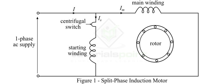
As the starting winding is made highly resistive whereas the main winding highly inductive. Consequently, the currents $\mathit{I_{s}}$ and $\mathit{I_{m}}$ in the two windings have a reasonable phase difference of about 25 to 30. As a result, a weak revolving magnetic field is produced inside the motor which starts it.
Capacitor Start Induction Motor
The type of single-phase induction motor in which a capacitor C is connected in series with the starting winding as shown in Figure-2. This capacitor is called starting capacitor. The value of starting capacitor is so chosen that the starting current $\mathit{I_{s}}$ leads the current $\mathit{I_{m}}$ through the main winding by about 80.
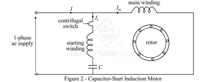
Once the motor attains about 75% of the rated speed, a centrifugal switch isolates the starting winding from the circuit. The motor then operates as a single-phase induction motor and continues to accelerate till it reaches the normal speed. Therefore, in this type of single-phase induction motor, the capacitor in series with the starting winding introduces a phase shift between the two windings so that the motor can start itself.
Capacitor-Start Capacitor Run Induction Motor
This motor is almost identical to a capacitor-start induction motor except that the starting winding is not disconnected from the motor circuit. Therefore, in case of capacitor-start capacitor-run induction motor, both the windings (starting winding & main winding) remain connected to the supply during starting as well as running period.
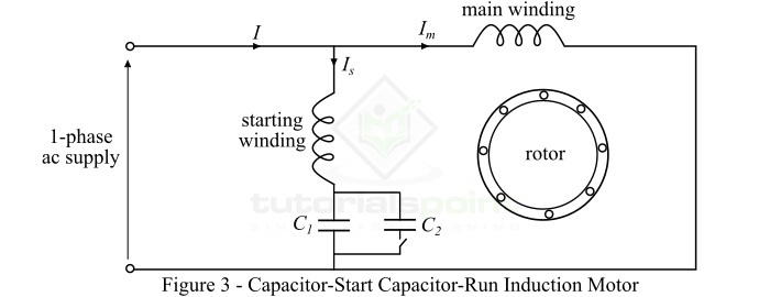
In this motor, two capacitors C1 and C2 are used in the starting winding as show in Figure-3. The capacitor C1 having small capacitance value is used for optimum running of the motor and hence permanently connected in series with the starting winding, whereas the larger capacitor C2 is connected in parallel with C1 and it remains in the circuit during starting period only. The starting capacitor C2 is isolated from the circuit by a centrifugal switch when the motor reaches about 75% of rated speed. The motor is then runs as a single-phase induction motor.
Applications of Single-Phase Induction Motors
Single-phase induction motors are mainly used in domestic and commercial appliances like fans, ACs, refrigerators, air-cooler, washing machines, etc. Given below are some of the applications of different kinds of single-phase induction motors −
- Split-Phase Induction Motors − These motors are best suited for moderate starting-torque applications like fans, washing machines, oil burners, small machine tools, etc.
- Capacitor-Start Induction Motors − These motors are suitable for applications that require relatively high-starting torque like compressors, large fans, pumps and high-inertia loads, etc.
- Capacitor-Start Capacitor-Run Induction Motors − These motors are suitable for constant torque, and vibration free applications like in hospital appliances, studio equipment and in many other appliances that are used in such areas where silence is important.