- Electrical Machines - Home
- Basic Concepts
- Electromechanical Energy Conversion
- Energy Stored in Magnetic Field
- Singly-Excited and Doubly Excited Systems
- Rotating Electrical Machines
- Electrical Machines Types
- Faraday’s Laws of Electromagnetic Induction
- Concept of Induced EMF
- Fleming's Left Hand and Right Hand Rules
- Transformers
- Electrical Transformer
- Construction of Transformer
- EMF Equation of Transformer
- Turns Ratio and Voltage Transformation Ratio
- Ideal Transformer
- Practical Transformer
- Ideal and Practical Transformers
- Transformer on DC
- Losses in a Transformer
- Efficiency of Transformer
- 3-Phase Transformer
- Types of Transformers
- More on Transformers
- Transformer Working Principle
- Single-Phase Transformer Working Principle
- 3-Phase Transformer Principle
- 3-Phase Induction Motor Torque-Slip
- 3-Phase Induction Motor Torque-Speed
- 3-Phase Transformer Harmonics
- Double-Star Connection (3-6 Phase)
- Double-delta Connection (3-6 Phase)
- Transformer Ratios
- Voltage Regulation
- Delta-Star Connection (3-Phase)
- Star-Delta Connection (3-Phase)
- Autotransformer Conversion
- Back-to-back Test (Sumpner's Test)
- Transformer Voltage Drop
- Autotransformer Output
- Open and Short Circuit Test
- 3-Phase Autotransformer
- Star-Star Connection
- 6-Phase Diametrical Connections
- Circuit Test (Three-Winding)
- Potential Transformer
- Transformers Parallel Operation
- Open Delta (V-V) Connection
- Autotransformer
- Current Transformer
- No-Load Current Wave
- Transformer Inrush Current
- Transformer Vector Groups
- 3 to 12-Phase Transformers
- Scott-T Transformer Connection
- Transformer kVA Rating
- Three-Winding Transformer
- Delta-Delta Connection Transformer
- Transformer DC Supply Issue
- Equivalent Circuit Transformer
- Simplified Equivalent Circuit of Transformer
- Transformer No-Load Condition
- Transformer Load Condition
- OTI WTI Transformer
- CVT Transformer
- Isolation vs Regular Transformer
- Dry vs Oil-Filled
- DC Machines
- Construction of DC Machines
- Types of DC Machines
- Working Principle of DC Generator
- EMF Equation of DC Generator
- Derivation of EMF Equation DC Generator
- Types of DC Generators
- Working Principle of DC Motor
- Back EMF in DC Motor
- Types of DC Motors
- Losses in DC Machines
- Applications of DC Machines
- More on DC Machines
- DC Generator
- DC Generator Armature Reaction
- DC Generator Commutator Action
- Stepper vs DC Motors
- DC Shunt Generators Critical Resistance
- DC Machines Commutation
- DC Motor Characteristics
- Synchronous Generator Working Principle
- DC Generator Characteristics
- DC Generator Demagnetizing & Cross-Magnetizing
- DC Motor Voltage & Power Equations
- DC Generator Efficiency
- Electric Breaking of DC Motors
- DC Motor Efficiency
- Four Quadrant Operation of DC Motors
- Open Circuit Characteristics of DC Generators
- Voltage Build-Up in Self-Excited DC Generators
- Types of Armature Winding in DC Machines
- Torque in DC Motors
- Swinburne’s Test of DC Machine
- Speed Control of DC Shunt Motor
- Speed Control of DC Series Motor
- DC Motor of Speed Regulation
- Hopkinson's Test
- Permanent Magnet DC Motor
- Permanent Magnet Stepper Motor
- DC Servo Motor Theory
- DC Series vs Shunt Motor
- BLDC Motor vs PMSM Motor
- Induction Motors
- Introduction to Induction Motor
- Single-Phase Induction Motor
- 3-Phase Induction Motor
- Construction of 3-Phase Induction Motor
- 3-Phase Induction Motor on Load
- Characteristics of 3-Phase Induction Motor
- Speed Regulation and Speed Control
- Methods of Starting 3-Phase Induction Motors
- More on Induction Motors
- 3-Phase Induction Motor Working Principle
- 3-Phase Induction Motor Rotor Parameters
- Double Cage Induction Motor Equivalent Circuit
- Induction Motor Equivalent Circuit Models
- Slip Ring vs Squirrel Cage Induction Motors
- Single-Cage vs Double-Cage Induction Motor
- Induction Motor Equivalent Circuits
- Induction Motor Crawling & Cogging
- Induction Motor Blocked Rotor Test
- Induction Motor Circle Diagram
- 3-Phase Induction Motors Applications
- 3-Phase Induction Motors Torque Ratios
- Induction Motors Power Flow Diagram & Losses
- Determining Induction Motor Efficiency
- Induction Motor Speed Control by Pole-Amplitude Modulation
- Induction Motor Inverted or Rotor Fed
- High Torque Cage Motors
- Double-Cage Induction Motor Torque-Slip Characteristics
- 3-Phase Induction Motors Starting Torque
- 3-phase Induction Motor - Rotor Resistance Starter
- 3-phase Induction Motor Running Torque
- 3-Phase Induction Motor - Rotating Magnetic Field
- Isolated Induction Generator
- Capacitor-Start Induction Motor
- Capacitor-Start Capacitor-Run Induction Motor
- Winding EMFs in 3-Phase Induction Motors
- Split-Phase Induction Motor
- Shaded Pole Induction Motor
- Repulsion-Start Induction-Run Motor
- Repulsion Induction Motor
- PSC Induction Motor
- Single-Phase Induction Motor Performance Analysis
- Linear Induction Motor
- Single-Phase Induction Motor Testing
- 3-Phase Induction Motor Fault Types
- Synchronous Machines
- Introduction to 3-Phase Synchronous Machines
- Construction of Synchronous Machine
- Working of 3-Phase Alternator
- Armature Reaction in Synchronous Machines
- Output Power of 3-Phase Alternator
- Losses and Efficiency of an Alternator
- Losses and Efficiency of 3-Phase Alternator
- Working of 3-Phase Synchronous Motor
- Equivalent Circuit and Power Factor of Synchronous Motor
- Power Developed by Synchronous Motor
- More on Synchronous Machines
- AC Motor Types
- Induction Generator (Asynchronous Generator)
- Synchronous Speed Slip of 3-Phase Induction Motor
- Armature Reaction in Alternator at Leading Power Factor
- Armature Reaction in Alternator at Lagging Power Factor
- Stationary Armature vs Rotating Field Alternator Advantages
- Synchronous Impedance Method for Voltage Regulation
- Saturated & Unsaturated Synchronous Reactance
- Synchronous Reactance & Impedance
- Significance of Short Circuit Ratio in Alternator
- Hunting Effect Alternator
- Hydrogen Cooling in Synchronous Generators
- Excitation System of Synchronous Machine
- Equivalent Circuit Phasor Diagram of Synchronous Generator
- EMF Equation of Synchronous Generator
- Cooling Methods for Synchronous Generators
- Assumptions in Synchronous Impedance Method
- Armature Reaction at Unity Power Factor
- Voltage Regulation of Alternator
- Synchronous Generator with Infinite Bus Operation
- Zero Power Factor of Synchronous Generator
- Short Circuit Ratio Calculation of Synchronous Machines
- Speed-Frequency Relationship in Alternator
- Pitch Factor in Alternator
- Max Reactive Power in Synchronous Generators
- Power Flow Equations for Synchronous Generator
- Potier Triangle for Voltage Regulation in Alternators
- Parallel Operation of Alternators
- Load Sharing in Parallel Alternators
- Slip Test on Synchronous Machine
- Constant Flux Linkage Theorem
- Blondel's Two Reaction Theory
- Synchronous Machine Oscillations
- Ampere Turn Method for Voltage Regulation
- Salient Pole Synchronous Machine Theory
- Synchronization by Synchroscope
- Synchronization by Synchronizing Lamp Method
- Sudden Short Circuit in 3-Phase Alternator
- Short Circuit Transient in Synchronous Machines
- Power-Angle of Salient Pole Machines
- Prime-Mover Governor Characteristics
- Power Input of Synchronous Generator
- Power Output of Synchronous Generator
- Power Developed by Salient Pole Motor
- Phasor Diagrams of Cylindrical Rotor Moto
- Synchronous Motor Excitation Voltage Determination
- Hunting Synchronous Motor
- Self-Starting Synchronous Motor
- Unidirectional Torque Production in Synchronous Motor
- Effect of Load Change on Synchronous Motor
- Field Excitation Effect on Synchronous Motor
- Output Power of Synchronous Motor
- Input Power of Synchronous Motor
- V Curves & Inverted V Curves of Synchronous Motor
- Torque in Synchronous Motor
- Construction of 3-Phase Synchronous Motor
- Synchronous Motor
- Synchronous Condenser
- Power Flow in Synchronous Motor
- Types of Faults in Alternator
- Miscellaneous Topics
- Electrical Generator
- Determining Electric Motor Load
- Solid State Motor Starters
- Characteristics of Single-Phase Motor
- Types of AC Generators
- Three-Point Starter
- Four-Point Starter
- Ward Leonard Speed Control Method
- Pole Changing Method
- Stator Voltage Control Method
- DOL Starter
- Star-Delta Starter
- Hysteresis Motor
- 2-Phase & 3-Phase AC Servo Motors
- Repulsion Motor
- Reluctance Motor
- Stepper Motor
- PCB Motor
- Single-Stack Variable Reluctance Stepper Motor
- Schrage Motor
- Hybrid Schrage Motor
- Multi-Stack Variable Reluctance Stepper Motor
- Universal Motor
- Step Angle in Stepper Motor
- Stepper Motor Torque-Pulse Rate Characteristics
- Distribution Factor
- Electrical Machines Basic Terms
- Synchronizing Torque Coefficient
- Synchronizing Power Coefficient
- Metadyne
- Motor Soft Starter
- CVT vs PT
- Metering CT vs Protection CT
- Stator and Rotor in Electrical Machines
- Electric Motor Winding
- Electric Motor
- Useful Resources
- Quick Guide
- Resources
- Discussion
Electrical Machines - CVT Transformer
In electrical engineering, CVT stands for Capacitive Voltage Transformer. It is a specially designed electrical transformer used for stepping down the high voltage of incoming supply to a low voltage for metering, protection and automation. It is an important component of an electrical substation. Sometimes, CVT is also referred to as CPT (Capacitive Potential Transformer).
In this article, we will learn about CVT, its function, advantages, and applications in electrical power systems. So, lets start with the basic definition of CVT.
What is a CVT Transformer?
CVT or Capacitive Voltage Transformer is an instrument transformer used in electrical systems, mostly in substations, for reducing the voltage to a level suitable for measurement and protection purposes.
Therefore, a CVT is a voltage stepdown transformer that reduces the high voltage to a low voltage. CVT is basically a highinsulated transformer that mainly used for measurement of highvoltage of greater than 100 kV.
When we compare a highinsulated transformer with a standard transformer, the highinsulated transformers are very expensive. Therefore, to reduce the cost of these highinsulated transformers, a capacitive voltage transformer technology is used. In simple words, we can say that a CVT provides same level of insulation and have a lower price as compare to another type of highinsulated transformer.
Working Principle of CVT Transformer
Let us now understand the basic construction and working of a capacitive voltage transformer.
A typical capacitive voltage transformer consists of the following three main components
- Capacitive Voltage Divider
- Auxiliar Transformer
- Inductive Element
The circuit diagram of the CVT is shown in the following figure.
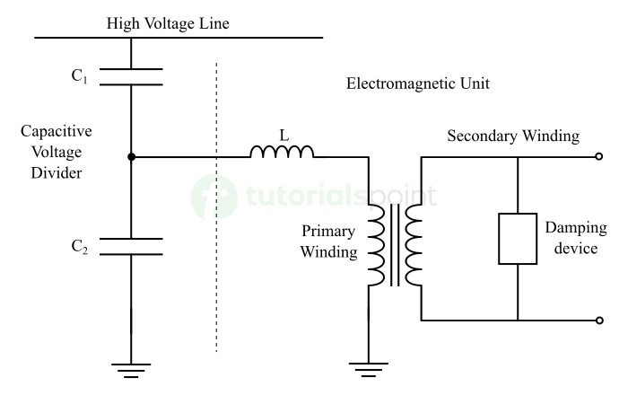
The main function of the capacitive voltage divider and the auxiliary transformer is to reduce the high voltage to a low value.
The capacitive voltage divider is connected across the transmission line and in series with the primary winding of the auxiliary transformer. Therefore, the auxiliary transformer gets the input supply from the output of the capacitive voltage divider.
The capacitive voltage divider consists of two capacitors namely, C1 and C2 Among these capacitors, the capacitor C2 which is placed closer to the ground terminal have a higher capacitance value as compared to the capacitor C1. Due to this high capacitance of C2 , the impedance of this part of the divider circuit becomes low. Thus, it produces a reduced voltage at its output.
This low voltage is then transmitted to the primary winding of the auxiliary transformer which is further stepped down by the transformer and supplied to a metering unit for measurement. It is also important to note that the metering unit behaves a resistive load.
So, we can observe that the voltage divider on the input side is of capacitive nature while the metering unit on the output side is of resistive nature. This creates a phase shift between the input and output voltages and affects the measurement. To overcome this issue, a compensating inductor is connected in series with the primary winding of the auxiliary transformer as shown in the circuit diagram.
The inductance value L of this compensating inductor is given by,
$$\mathrm{L \: = \: \frac{1}{\omega^2(C_{1} \:+\: C_{2})}}$$
This inductance value L consists of the leakage flux of the auxiliary transformer. Therefore, it also compensates the voltage drops that occur in the auxiliary transformer due to reduction in the current from the capacitive voltage divider. But in practice, this compensation is not possible due to inductive losses.
Voltage Transformation Ratio of CVT Transformer
The voltage transformation ratio of a CVT transformer is given by,
$$\mathrm{\frac{V_{\circ}}{V_1}\:=\: \left[\frac{C_1}{C_1 \:+\: C_2}\right]\:\times \: \frac{N_2}{N_1}}$$
Here,
- V1 is the input voltage
- V° is the output voltage
- N2 is the secondary winding turns of the auxiliary transformer
- N1 is the primary winding turns of the auxiliary transformer
Since, for a CVT transformer, C2 > C1, then the value of [C1 / (C1 + C2)] will be low. Hence, this decreases the value of voltage.
Name Plate Details of CVT Transformer
The nameplate of the capacitive voltage transformer (CVT) has the following parameters marked on it
- Manufacturers Information
- Insulation Level
- Standard
- Capacitance
- Primary Capacitance
- Secondary Capacitance
- Highest System Voltage (HSV)
- Voltage Factor
- Frequency
- Simultaneous Burden
- Thermal Burden
- Total Weight
- Total oil Weight
- Manufacturing Year
- Primary and Secondary Voltages
- VA Burden
- Accuracy Class
- Fuse rating
Let us discuss about each of these parameters in detail.
Manufacturers Information
The nameplate of CVT contains details about the manufacturer. This information mainly includes the name of the manufacturer, logo, and contact details.
Insulation Level
This information has two values where one is the RMS value and the other is the peak value. The RMS value mentioned is known as power frequency withstand voltage and is given in kVrms.
The peak value mentioned is known as the lighting impulse voltage and is given in kVpeak. These voltage values are used for determining the insulation characteristics of the CVT and are known as its insulation levels.
Standard
This parameter provides information about industry standard according which the CVT is manufactured.
Capacitance
A CVT has a combination of two capacitors C1 and C2 connected in series. The capacitance is the equivalent capacitance of these two capacitors which is provided on the nameplate.
Primary Capacitance
In the CVT, the capacitance of the capacitor C1 is called the primary capacitance. Its value is provided on the nameplate of the CVT transformer.
Secondary Capacitance
The capacitance of the capacitor C2 is known as secondary capacitance. Its value is also given on the name plate of the CVT transformer.
Highest System Voltage (HSV)
The highest system voltage is the voltage for the CVT transformer is designed to operate. This voltage is also known as rated voltage of the CVT and its value is always provided on the nameplate.
Voltage Factor
Voltage factor is nothing but the value of highest voltage that the CVT can handle for a specific time. It is mentioned on the name plate of the CVT in Per Unit System.
For example, if on the nameplate, it is given that 1.15 continuous and 1.3 for 25 seconds. Then, it indicates that the CVT can handle 115% of the rated voltage continuously and it can handle 130% of the rated voltage for 25 seconds.
Frequency
It is the rated frequency of the supply voltage at which the power is generated, transmitted, and distributed. It can be 50 Hz or 60 Hz depending on the supply system used in the country.
Simultaneous Burden
This parameter of the CVT nameplate provides information about the VA that can be taken from all the secondary windings at the same time without affecting the accuracy of any of the cores.
It is an important parameter because the burden connected to one of the secondary windings can affect the accuracy of the other secondary winding. This is mainly because the secondary windings of the CVT are wound on the same core.
Thermal Burden
It is the value of total amount of VA that can be taken from the CVT transformer at a time without increasing its temperature above a particular limit defined by the industry standard.
For example, if the thermal burden of 250 VA is mentioned on the nameplate of a CVT, then it shows that 250 VA can be taken from the CVT without exceeding the specified temperature limit.
Total Weight
This parameter provides the total weight of the CVT transformer in kilograms.
Total Oil Weight
This parameter gives the weight of the oil used in the CVT transformer for insulation and cooling purpose.
Manufacturing Year
This parameter provides the detail of year in which the CVT transformer is manufactured.
Primary and Secondary Voltages
This parameter shows the per phase voltage of the CVTs primary and secondary windings.
VA Burden
Burden is the total VA connected to the secondary winding of the CVT transformer. On the nameplate, the burden is given that we can connect to each winding of the CVT.
Accuracy Class
CVT transformer is used in power systems for measurement and protection purposes. And, different windings are used for metering and protection. Therefore, different accuracy classes are specified for metering and protection purposes. The main purpose of accuracy class is to specify the tolerable error in the output.
For example, if a metering class of CVT has an accuracy class of 0.5, then it shows that the tolerable error in voltage can be equal to ± 0.5%.
Similarly, if we have a protection class of CVT and it has an accuracy class of 3P and the applied voltage is 2% of the rated voltage. Then, this shows that the error in the voltage of the CVT must be within ± 6%.
Fuse Rating
In a CVT, fuses are provided on the secondary side for protection purpose.
This is all about name plate details of a CVT transformer. Let us now discuss the major advantages and applications of CVT transformers.
Functions of CVT Transformer
A CVT transformer is used in power systems for the following purposes
- Accurate measurement of high voltages in power system.
- To provide voltage signals for monitoring and control applications.
- To detect abnormal conditions in the system and actuate the protection relays.
- For metering purposes.
- To filter out the harmonic components, etc.
Advantages of CVT Transformer
The main advantages of a capacitive voltage transformer are highlighted below
- CVT has a high accuracy in voltage measurement.
- CVTs can operate in a wide range of frequencies and hence these can be used in both AC and DC systems.
- CVTs have high insulation levels and thus can withstand very high voltages.
- CVTs require less maintenance. Hence, their operation cost is low.
- CVTs can be used with a wide range metering and protection devices.
- CVTs are less expensive than other highly insulated transformers.
- Due to compact size, CVTs require a less space for installation.
- CVTs are simple to design and manufacture.
Applications of CVT Transformer
CVT is primarily used for metering and protection purposes in power systems. The following are some major applications of CVT transformers
- CVT transformers are used for measuring high voltage in power systems for calculating energy consumption.
- CVTs are also used for protection purposes to detect abnormal conditions in the power system and operate the protection relays.
- In instrumentation and control, CVTs are used for monitoring and controlling the system voltage to improve the power system stability.
- In substation automation systems, CVTs are used for providing voltage signals for monitoring and controlling different automation components.
- CVTs are also employed in testing of highvoltage electrical systems.
This is all about CVT or Capacitive Voltage Transformer.
Conclusion
From the above discussion, we can conclude that a CVT is a high insulation instrument transformer used in power systems for metering and protection purposes. It is used because of its high accuracy and low cost as compared to other highly insulated transformers. In this article, I have explained major concepts related to CVT transformer.
FAQs Related to CVT Transformer
This section answers some most frequently asked questions related to capacitive voltage transformer (CVT)
1. What is the full form of CVT?
The full form of CVT is Capacitive Voltage Transformer. Sometimes, it is also expended as Capacitor Voltage Transformer.
2. What is the purpose of a CVT?
A CVT is used for the following two purposes
- Measurement of high voltages
- Protection of power system
3. Is the difference between VT and CVT?
VT stands for voltage transformer. A VT is a normal electromagnetic device that can stepup or stepdown the voltage. On the other hand, CVT is a voltage stepdown transformer which consists of a capacitive voltage divider along with a transformer for voltage stepdown purpose.
4. Why is CVT better?
The following are some key factors that make a CVT better
- Versatility, as it can perform measurement, protection, monitoring, control, and many other important functions.
- Less expensive as compared to other types of highly insulated transformers.
- Compact design, etc.
5. What are 3 benefits of CVT?
The following are the 3 main benefits of CVT
- Small size
- Low cost
- High accuracy