- Computer Graphics - Home
- Computer Graphics Basics
- Computer Graphics Applications
- Graphics APIs and Pipelines
- Computer Graphics Maths
- Sets and Mapping
- Solving Quadratic Equations
- Computer Graphics Trigonometry
- Computer Graphics Vectors
- Linear Interpolation
- Computer Graphics Devices
- Cathode Ray Tube
- Raster Scan Display
- Random Scan Device
- Phosphorescence Color CRT
- Flat Panel Displays
- 3D Viewing Devices
- Images Pixels and Geometry
- Color Models
- Line Generation
- Line Generation Algorithm
- DDA Algorithm
- Bresenham's Line Generation Algorithm
- Mid-point Line Generation Algorithm
- Circle Generation
- Circle Generation Algorithm
- Bresenham's Circle Generation Algorithm
- Mid-point Circle Generation Algorithm
- Ellipse Generation Algorithm
- Polygon Filling
- Polygon Filling Algorithm
- Scan Line Algorithm
- Flood Filling Algorithm
- Boundary Fill Algorithm
- 4 and 8 Connected Polygon
- Inside Outside Test
- 2D Transformation
- 2D Transformation
- Transformation Between Coordinate System
- Affine Transformation
- Raster Methods Transformation
- 2D Viewing
- Viewing Pipeline and Reference Frame
- Window Viewport Coordinate Transformation
- Viewing & Clipping
- Point Clipping Algorithm
- Cohen-Sutherland Line Clipping
- Cyrus-Beck Line Clipping Algorithm
- Polygon Clipping Sutherland–Hodgman Algorithm
- Text Clipping
- Clipping Techniques
- Bitmap Graphics
- 3D Viewing Transformation
- 3D Computer Graphics
- Parallel Projection
- Orthographic Projection
- Oblique Projection
- Perspective Projection
- 3D Transformation
- Rotation with Quaternions
- Modelling and Coordinate Systems
- Back-face Culling
- Lighting in 3D Graphics
- Shadowing in 3D Graphics
- 3D Object Representation
- Represnting Polygons
- Computer Graphics Surfaces
- Visible Surface Detection
- 3D Objects Representation
- Computer Graphics Curves
- Computer Graphics Curves
- Types of Curves
- Bezier Curves and Surfaces
- B-Spline Curves and Surfaces
- Data Structures For Graphics
- Triangle Meshes
- Scene Graphs
- Spatial Data Structure
- Binary Space Partitioning
- Tiling Multidimensional Arrays
- Color Theory
- Colorimetry
- Chromatic Adaptation
- Color Appearance
- Antialiasing
- Ray Tracing
- Ray Tracing Algorithm
- Perspective Ray Tracing
- Computing Viewing Rays
- Ray-Object Intersection
- Shading in Ray Tracing
- Transparency and Refraction
- Constructive Solid Geometry
- Texture Mapping
- Texture Values
- Texture Coordinate Function
- Antialiasing Texture Lookups
- Procedural 3D Textures
- Reflection Models
- Real-World Materials
- Implementing Reflection Models
- Specular Reflection Models
- Smooth-Layered Model
- Rough-Layered Model
- Surface Shading
- Diffuse Shading
- Phong Shading
- Artistic Shading
- Computer Animation
- Computer Animation
- Keyframe Animation
- Morphing Animation
- Motion Path Animation
- Deformation Animation
- Character Animation
- Physics-Based Animation
- Procedural Animation Techniques
- Computer Graphics Fractals
Modelling and 3D Coordinate Systems in Computer Graphics
Coordinate systems act as the backbone for 3D transformation and rotation. Coordinate systems help accurately model, manipulate, and render objects in a three-dimensional environment. In this chapter, we will see various coordinate systems used in 3D design, including the differences between right-hand and left-hand coordinate systems which are used in several software in 3D designs.
Coordinate Systems
In 3D design also in mathematics, a coordinate system defines how points in space are represented. In the most useful coordinate system, every point in 3D space is specified by three values (x, y, z) known as coordinates. These values correspond to distances along three perpendicular axes: the x-axis (horizontal), y-axis (vertical), and z-axis (depth).
Coordinate systems show a way to position and manipulate objects in a virtual environment. Without them, it would be impossible to specify where an object is located or how it should be oriented. There are various types of coordinate systems used in 3D design, each suited for different tasks and representations. We will explore them one by one in the following sections of this chapter.
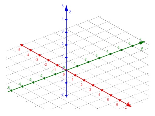
Cartesian Coordinate System
The Cartesian coordinate system is the most widely used system in 3D design. It consists of three perpendicular axes (x, y, z) that define a 3D space. Each point in this space is represented by three values corresponding to the distances along these axes from the origin (0, 0, 0).
Polar Coordinate System
The polar coordinate are used in 2D. A point is represented by angles and distances from a central origin.
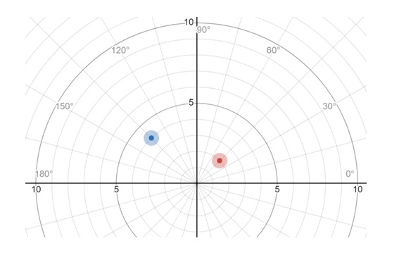
Here red point coordinate is (45, 2) and blue point is at (-45, -4)
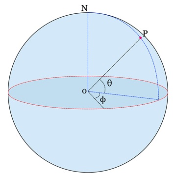
Spherical Coordinates
Spherical coordinates extend polar coordinates to three dimensions. It adds radial distance and two angles. Instead of specifying coordinates as (x, y, z), polar coordinates use a radius r and two angles (azimuthal) and (polar). This system is useful in cases where rotational symmetry is involved, such as modelling spherical objects or camera positioning.
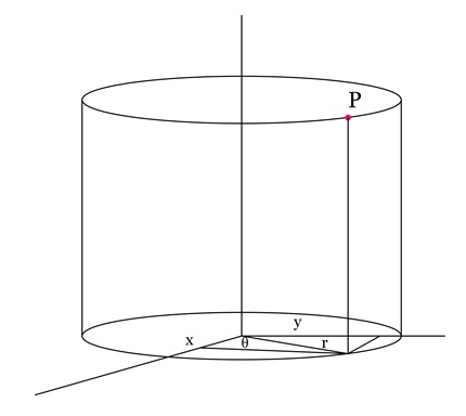
Cylindrical Coordinates
In cylindrical coordinates, a point in 3D space is described by a height along the z-axis, a radius from the z-axis, and an angle around the z-axis. This system is ideal for modelling objects like pipes, cylinders, or any structure that extends vertically while retaining circular symmetry in the horizontal plane.
Right-Hand and Left-Hand Coordinate Systems
One important aspect of 3D design is the choice between right-hand and left-hand coordinate systems. These systems define the orientation of the X, Y, and Z axes and have a significant impact on how objects are rendered and manipulated in a scene.
Right-Hand Coordinate System
In a right-hand coordinate system, the direction of the axes is determined using your right hand. If you point your thumb in the direction of the positive x-axis, your index finger in the direction of the positive y-axis, and your middle finger in the direction of the positive z-axis, you will have the orientation of the right-hand system.
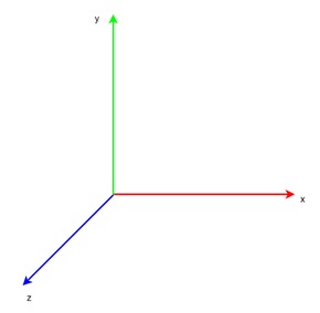
This system is widely used in many 3D graphics applications, including OpenGL. It offers an intuitive way to visualize and apply transformations such as rotations and translations.
Key Features of Right-Hand Coordinate System
Following are the key features of Right-Hand Coordinate System −
- The z-axis typically points out of the screen or towards the viewer.
- It's commonly used in most 3D software, making it the standard in many cases.
Left-Hand Coordinate System
In a left-hand coordinate system, the orientation of the axes is reversed compared to the right-hand system. To visualize this, point your left thumb along the positive x-axis, your index finger along the positive y-axis, and your middle finger along the positive z-axis.
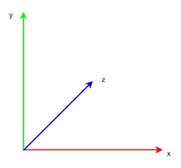
This system is often used in certain 3D applications and game engines, such as DirectX.
Key Features of Left-Hand Coordinate System
Following are the key features of Left-Hand Coordinate System −
- The z-axis usually points into the screen or away from the viewer.
- It's commonly used in specific applications like game development, where compatibility with certain engines or frameworks requires it.
Differences Between Right-Hand and Left-Hand Systems
The main difference between these systems lies in the direction of the z-axis. In the right-hand system, the positive z-axis points outward, while in the left-hand system, it points inward. This difference can lead to flipped models or mirrored transformations if the wrong system is used.
Understanding which system your software uses is crucial for correctly positioning and orienting objects in 3D space.
Why the Choice of Coordinate System Matters?
Choosing between a right-hand or left-hand system is more than just a technical detail. It affects:
- Camera views − The direction in which the camera looks will change depending on the coordinate system, which can influence how scenes are rendered.
- Modelling consistency − When working with models across different software platforms, inconsistent coordinate systems can lead to mirrored or incorrectly aligned objects.
- Animation and physics − Rotations and forces applied to objects will behave differently depending on the coordinate system, potentially causing problems in animations or simulations if not handled properly.
Modelling in 3D Design
Modelling is the process of creating a 3D representation of an object or scene. To do this effectively, understanding coordinate systems and how to manipulate objects within them is essential.
- Object Positioning − To create a 3D object, the first step is to define its position within the coordinate system. This involves specifying the object's coordinates in terms of x, y, and z. The origin (0, 0, 0) is typically the central reference point, and objects are positioned relative to it.
- Scaling and Transformation − Once an object is positioned, various transformations can be applied to it.
- Translation − Moves the object along one or more axes. For example, moving an object 5 units along the x-axis changes its x-coordinate.
- Rotation − Involves rotating an object around one or more of the coordinate axes. Rotation can be complex, especially when multiple axes are involved.
- Scaling − Adjusts the size of the object along each axis. Scaling can make objects larger or smaller, or even stretch them in one direction.
-
Local and World Coordinates − Objects in 3D space are often manipulated in both local and world coordinate systems −
- Local coordinates − These are the object's coordinates relative to its own origin. For example, when a car model is rotated around its own centre, this happens in local coordinates.
- World coordinates − These refer to the object's position in the overall scene. For example, moving a car model along the road requires adjusting its position in the world coordinate system.
Conclusion
In this chapter, we explained the fundamental role of coordinate systems in 3D design. We understood the different types of coordinate systems, including Cartesian, polar, spherical, and cylindrical systems, and the importance of choosing between right-hand and left-hand coordinate systems for 3D modelling.
We also covered the key aspects of modelling in 3D space, such as positioning, scaling, and rotating objects, and the distinction between local and world coordinates.