- Computer Graphics - Home
- Computer Graphics Basics
- Computer Graphics Applications
- Graphics APIs and Pipelines
- Computer Graphics Maths
- Sets and Mapping
- Solving Quadratic Equations
- Computer Graphics Trigonometry
- Computer Graphics Vectors
- Linear Interpolation
- Computer Graphics Devices
- Cathode Ray Tube
- Raster Scan Display
- Random Scan Device
- Phosphorescence Color CRT
- Flat Panel Displays
- 3D Viewing Devices
- Images Pixels and Geometry
- Color Models
- Line Generation
- Line Generation Algorithm
- DDA Algorithm
- Bresenham's Line Generation Algorithm
- Mid-point Line Generation Algorithm
- Circle Generation
- Circle Generation Algorithm
- Bresenham's Circle Generation Algorithm
- Mid-point Circle Generation Algorithm
- Ellipse Generation Algorithm
- Polygon Filling
- Polygon Filling Algorithm
- Scan Line Algorithm
- Flood Filling Algorithm
- Boundary Fill Algorithm
- 4 and 8 Connected Polygon
- Inside Outside Test
- 2D Transformation
- 2D Transformation
- Transformation Between Coordinate System
- Affine Transformation
- Raster Methods Transformation
- 2D Viewing
- Viewing Pipeline and Reference Frame
- Window Viewport Coordinate Transformation
- Viewing & Clipping
- Point Clipping Algorithm
- Cohen-Sutherland Line Clipping
- Cyrus-Beck Line Clipping Algorithm
- Polygon Clipping Sutherland–Hodgman Algorithm
- Text Clipping
- Clipping Techniques
- Bitmap Graphics
- 3D Viewing Transformation
- 3D Computer Graphics
- Parallel Projection
- Orthographic Projection
- Oblique Projection
- Perspective Projection
- 3D Transformation
- Rotation with Quaternions
- Modelling and Coordinate Systems
- Back-face Culling
- Lighting in 3D Graphics
- Shadowing in 3D Graphics
- 3D Object Representation
- Represnting Polygons
- Computer Graphics Surfaces
- Visible Surface Detection
- 3D Objects Representation
- Computer Graphics Curves
- Computer Graphics Curves
- Types of Curves
- Bezier Curves and Surfaces
- B-Spline Curves and Surfaces
- Data Structures For Graphics
- Triangle Meshes
- Scene Graphs
- Spatial Data Structure
- Binary Space Partitioning
- Tiling Multidimensional Arrays
- Color Theory
- Colorimetry
- Chromatic Adaptation
- Color Appearance
- Antialiasing
- Ray Tracing
- Ray Tracing Algorithm
- Perspective Ray Tracing
- Computing Viewing Rays
- Ray-Object Intersection
- Shading in Ray Tracing
- Transparency and Refraction
- Constructive Solid Geometry
- Texture Mapping
- Texture Values
- Texture Coordinate Function
- Antialiasing Texture Lookups
- Procedural 3D Textures
- Reflection Models
- Real-World Materials
- Implementing Reflection Models
- Specular Reflection Models
- Smooth-Layered Model
- Rough-Layered Model
- Surface Shading
- Diffuse Shading
- Phong Shading
- Artistic Shading
- Computer Animation
- Computer Animation
- Keyframe Animation
- Morphing Animation
- Motion Path Animation
- Deformation Animation
- Character Animation
- Physics-Based Animation
- Procedural Animation Techniques
- Computer Graphics Fractals
Viewing Pipeline and Concept of Reference Frame
We have covered several concepts in this tutorial including transformation and simple shape generating algorithms. Sometimes we need a certain window within which we display the graphics, for which we need to learn the concept of viewing. It involves selecting a part to display and mapping this selection to the display area, called the viewport. In this chapter, we will see the viewing pipeline and the concept of reference frames.
Basics of the Viewing Pipeline
When we talk about viewing we need the idea of world and local coordinates that we have seen in the previous articles. In short world coordinate system represents the entire virtual space in a computer graphics application. This space could be a game world, a city layout, or any other virtual environment. The world coordinate system defines the positions of objects and allows us to interact with and manipulate them.
- Window − We do not always want to display the entire world at once. Instead, we select a portion of the world for display, which is called the window. The window defines what part of the world will be visible on the screen.
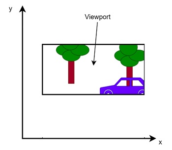
- Viewport − Once the window is selected, we need to display it on the screen. The area on the screen where this window is displayed is called the viewport. The viewport is the part of the display device (like our monitor or a TV) where the selected window is shown.
Example to Understand Window and Viewport
Let us assume the example scene, where we have a car and a tree. The entire scene is known as world. Now if we pick a selected region, a bounding box inside which we want to see, that is the window.
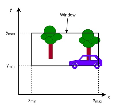
Here on the scene, we have defined a window. For that we need four parameters, xmin, ymin, xmax and ymax.
The view we can see through the window is called the viewport.
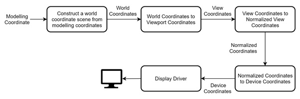
Viewing Pipeline
Let us see the pipeline that is used to display an image from scene to a viewport.
Let us see these one by one.
Construct a World Coordinate Scene from Modelling Coordinates
The first step is to construct a scene in the world coordinate system. When designing a 3D model or a 2D scene, we work with modelling coordinates. These coordinates are local to the individual objects in the scene. Each object has its own coordinate system, which needs to be transformed into the global or world coordinate system.
For example, in a game, each character or object might have its own local coordinate system, but when placed in the game world, these coordinates must be transformed to fit within the overall world scene.
World Coordinates to Viewport Coordinates
Once the world scene is constructed, we need to decide which part of the scene we want to display. This is done by defining a window in the world coordinate system. The window specifies the part of the world scene that will be shown to the user. After the window is selected, we must map it to the viewport. The viewport represents the area on the output device (for instance, the screen) where the selected portion of the world will be displayed.
- View Coordinates to Normalized View Coordinates − The next step is to normalize the view coordinates. Normalization is a important because it ensures that the coordinates fit within a standardized range. Normally, the viewport coordinates are transformed into a normalized coordinate system where the x and y values are between 0 and 1. Normalization simplifies further processing because working within a bounded range is easier for many operations.
- Normalized Coordinates to Device Coordinates − TAfter normalization, we need to convert the normalized view coordinates into device coordinates. This transformation is needed so that the graphical data is correctly positioned on the output device. The device coordinates represent the actual positions on the screen, printer, or any other output hardware.
- Display Driver − T Finally, the display driver plays a role in rendering the transformed coordinates on the actual device. The display driver takes the device coordinates and converts them into a format suitable for the display.
Reference Frame in the Viewing Pipeline
Let us see another important concept called the reference frame. This is a concept that helps in managing multiple coordinate systems. In the viewing pipeline, we use reference frames to define how objects in one coordinate system relate to another. For example, objects in the local coordinate system (the coordinate system relative to the object itself) must be transformed into the world coordinate system (the overall environment).
After selecting the window in the world coordinate system, we then transform the window to the device coordinate system using a reference frame. The object to be correctly placed and displayed on the screen with this.
The reference frame helps in managing transformations between different systems.
Conclusion
In this chapter, we explained the viewing pipeline and the concept of reference frames in computer graphics. We saw the basics of the world coordinate system, the window, and the viewport. We also explained the pipeline in detail with its steps. Lastly, we touched on the role of reference frames in managing transformations between coordinate systems.