- Computer Graphics - Home
- Computer Graphics Basics
- Computer Graphics Applications
- Graphics APIs and Pipelines
- Computer Graphics Maths
- Sets and Mapping
- Solving Quadratic Equations
- Computer Graphics Trigonometry
- Computer Graphics Vectors
- Linear Interpolation
- Computer Graphics Devices
- Cathode Ray Tube
- Raster Scan Display
- Random Scan Device
- Phosphorescence Color CRT
- Flat Panel Displays
- 3D Viewing Devices
- Images Pixels and Geometry
- Color Models
- Line Generation
- Line Generation Algorithm
- DDA Algorithm
- Bresenham's Line Generation Algorithm
- Mid-point Line Generation Algorithm
- Circle Generation
- Circle Generation Algorithm
- Bresenham's Circle Generation Algorithm
- Mid-point Circle Generation Algorithm
- Ellipse Generation Algorithm
- Polygon Filling
- Polygon Filling Algorithm
- Scan Line Algorithm
- Flood Filling Algorithm
- Boundary Fill Algorithm
- 4 and 8 Connected Polygon
- Inside Outside Test
- 2D Transformation
- 2D Transformation
- Transformation Between Coordinate System
- Affine Transformation
- Raster Methods Transformation
- 2D Viewing
- Viewing Pipeline and Reference Frame
- Window Viewport Coordinate Transformation
- Viewing & Clipping
- Point Clipping Algorithm
- Cohen-Sutherland Line Clipping
- Cyrus-Beck Line Clipping Algorithm
- Polygon Clipping Sutherland–Hodgman Algorithm
- Text Clipping
- Clipping Techniques
- Bitmap Graphics
- 3D Viewing Transformation
- 3D Computer Graphics
- Parallel Projection
- Orthographic Projection
- Oblique Projection
- Perspective Projection
- 3D Transformation
- Rotation with Quaternions
- Modelling and Coordinate Systems
- Back-face Culling
- Lighting in 3D Graphics
- Shadowing in 3D Graphics
- 3D Object Representation
- Represnting Polygons
- Computer Graphics Surfaces
- Visible Surface Detection
- 3D Objects Representation
- Computer Graphics Curves
- Computer Graphics Curves
- Types of Curves
- Bezier Curves and Surfaces
- B-Spline Curves and Surfaces
- Data Structures For Graphics
- Triangle Meshes
- Scene Graphs
- Spatial Data Structure
- Binary Space Partitioning
- Tiling Multidimensional Arrays
- Color Theory
- Colorimetry
- Chromatic Adaptation
- Color Appearance
- Antialiasing
- Ray Tracing
- Ray Tracing Algorithm
- Perspective Ray Tracing
- Computing Viewing Rays
- Ray-Object Intersection
- Shading in Ray Tracing
- Transparency and Refraction
- Constructive Solid Geometry
- Texture Mapping
- Texture Values
- Texture Coordinate Function
- Antialiasing Texture Lookups
- Procedural 3D Textures
- Reflection Models
- Real-World Materials
- Implementing Reflection Models
- Specular Reflection Models
- Smooth-Layered Model
- Rough-Layered Model
- Surface Shading
- Diffuse Shading
- Phong Shading
- Artistic Shading
- Computer Animation
- Computer Animation
- Keyframe Animation
- Morphing Animation
- Motion Path Animation
- Deformation Animation
- Character Animation
- Physics-Based Animation
- Procedural Animation Techniques
- Computer Graphics Fractals
Ray Tracing Algorithm in Computer Graphics
Ray tracing is an interesting topic in 3D graphics that is used for generating realistic 2D images of 3D scenes. This algorithm simulates the way how light interacts with objects to produce shadows, reflections, and refractions. In this chapter, we will cover the basics of ray tracing, discuss its main components, and provide a detailed example of how it works for a detailed understanding.
What is Ray Tracing?
Ray tracing is a rendering technique used to create high-quality images by simulating how light rays travel through a scene. It is an image-order algorithm. This means it computes each pixel of the image one at a time. Each pixel "looks" in a different direction, and any object that is seen by a pixel must intersect the viewing ray a line that emanates from the viewpoint in the direction the pixel is looking.
The goal of ray tracing is to find the nearest object intersecting the viewing ray and compute the color of that intersection point based on the lighting and other properties of the scene.
Key Features of Ray Tracing
Some of the key features of Ray Tracing include the following −
- Accurate shadow and reflection computation.
- Produces realistic images with complex lighting effects.
- Works with various shading techniques to produce visually appealing results.
Components of the Ray Tracing Algorithm
The ray-tracing algorithm can be broken down into three main components −
- Ray Generation − Ray generation computes the origin and direction of each pixel’s viewing ray. This is based on the camera geometry and defines where each ray starts and in which direction it travels.
- Ray Intersection − In this step, the algorithm finds the closest object intersecting the viewing ray. This object is the one that will be visible at that pixel’s position in the final image. The intersection point is used to determine which object blocks the view of others behind it.
- Shading − After determining the intersection point, shading is performed to compute the color of the pixel. The shading computation takes into account various factors, such as the intersection point, surface normal, lighting, and material properties.
Basic Ray Tracing Algorithm
Here is the Pseudocode for the Basic Ray Tracing Algorithm −
for each pixel do
    compute viewing ray
    find first object hit by ray and its surface normal n
    set pixel color to value computed from hit point, light, and n
end for
This structure of the basic ray-tracing algorithm shows how the algorithm processes each pixel one by one to produce a final image.
Example of Ray Tracing
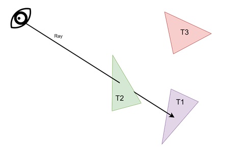
Let us see one example for ray tracing. Assume we have a camera looking at a scene containing three triangles. The goal is to determine which triangle is visible through each pixel and then shade it accordingly.
Step 1: Ray Generation
For each pixel in the image, a ray is generated starting from the camera’s viewpoint. This ray points in the direction of the pixel’s position on the image plane.
Step 2: Ray Intersection
Each ray is "traced" into the scene to find the first object it hits. For example, if a ray intersects two triangles, T1 and T2, but T2 is closer to the camera, then T2 is the object seen through that pixel.
Step 3: Shading
Once the closest object is identified, shading is performed to compute the pixel’s color. The color is determined based on the intersection point, the surface normal at that point, and the lighting in the scene.
This process is repeated for every pixel in an image that accurately represents the scene as viewed from the camera’s perspective.
Perspective in Ray Tracing
Perspective is an essential concept in ray tracing and it determines how 3D objects are projected onto a 2D image. The most common approach is linear perspective, which makes straight lines in the scene appear as straight lines in the image. This is achieved by projecting 3D objects onto an image plane in such a way that objects farther from the viewpoint appear smaller. We will learn the perspective in greater detail in the next article for ray tracing.
Computing Viewing Rays
Computing viewing rays is a one of the most important step in ray tracing. The camera geometry, including the viewpoint and image plane, determines how rays are generated. A ray is represented mathematically as an origin point and a direction vector. This representation allows the ray to be traced from the camera to any point in the scene.
For a perspective view, all rays originate from the same viewpoint but point in different directions based on the pixels position on the image plane. This creates a realistic sense of depth, as objects farther from the camera appear smaller in the final image.
Conclusion
In this chapter, we covered the basic ray-tracing algorithm used in computer graphics. We understood the concept of ray tracing and its key features. Then, we broke down the algorithm into its core components: ray generation, ray intersection, and shading. We provided a simple example to illustrate how the algorithm works in practice.