- Computer Graphics - Home
- Computer Graphics Basics
- Computer Graphics Applications
- Graphics APIs and Pipelines
- Computer Graphics Maths
- Sets and Mapping
- Solving Quadratic Equations
- Computer Graphics Trigonometry
- Computer Graphics Vectors
- Linear Interpolation
- Computer Graphics Devices
- Cathode Ray Tube
- Raster Scan Display
- Random Scan Device
- Phosphorescence Color CRT
- Flat Panel Displays
- 3D Viewing Devices
- Images Pixels and Geometry
- Color Models
- Line Generation
- Line Generation Algorithm
- DDA Algorithm
- Bresenham's Line Generation Algorithm
- Mid-point Line Generation Algorithm
- Circle Generation
- Circle Generation Algorithm
- Bresenham's Circle Generation Algorithm
- Mid-point Circle Generation Algorithm
- Ellipse Generation Algorithm
- Polygon Filling
- Polygon Filling Algorithm
- Scan Line Algorithm
- Flood Filling Algorithm
- Boundary Fill Algorithm
- 4 and 8 Connected Polygon
- Inside Outside Test
- 2D Transformation
- 2D Transformation
- Transformation Between Coordinate System
- Affine Transformation
- Raster Methods Transformation
- 2D Viewing
- Viewing Pipeline and Reference Frame
- Window Viewport Coordinate Transformation
- Viewing & Clipping
- Point Clipping Algorithm
- Cohen-Sutherland Line Clipping
- Cyrus-Beck Line Clipping Algorithm
- Polygon Clipping Sutherland–Hodgman Algorithm
- Text Clipping
- Clipping Techniques
- Bitmap Graphics
- 3D Viewing Transformation
- 3D Computer Graphics
- Parallel Projection
- Orthographic Projection
- Oblique Projection
- Perspective Projection
- 3D Transformation
- Rotation with Quaternions
- Modelling and Coordinate Systems
- Back-face Culling
- Lighting in 3D Graphics
- Shadowing in 3D Graphics
- 3D Object Representation
- Represnting Polygons
- Computer Graphics Surfaces
- Visible Surface Detection
- 3D Objects Representation
- Computer Graphics Curves
- Computer Graphics Curves
- Types of Curves
- Bezier Curves and Surfaces
- B-Spline Curves and Surfaces
- Data Structures For Graphics
- Triangle Meshes
- Scene Graphs
- Spatial Data Structure
- Binary Space Partitioning
- Tiling Multidimensional Arrays
- Color Theory
- Colorimetry
- Chromatic Adaptation
- Color Appearance
- Antialiasing
- Ray Tracing
- Ray Tracing Algorithm
- Perspective Ray Tracing
- Computing Viewing Rays
- Ray-Object Intersection
- Shading in Ray Tracing
- Transparency and Refraction
- Constructive Solid Geometry
- Texture Mapping
- Texture Values
- Texture Coordinate Function
- Antialiasing Texture Lookups
- Procedural 3D Textures
- Reflection Models
- Real-World Materials
- Implementing Reflection Models
- Specular Reflection Models
- Smooth-Layered Model
- Rough-Layered Model
- Surface Shading
- Diffuse Shading
- Phong Shading
- Artistic Shading
- Computer Animation
- Computer Animation
- Keyframe Animation
- Morphing Animation
- Motion Path Animation
- Deformation Animation
- Character Animation
- Physics-Based Animation
- Procedural Animation Techniques
- Computer Graphics Fractals
Scene Graphs in Computer Graphics
Scene graphs are used to manage and organize complex scenes. They help arrange objects, especially when transformations like rotation, translation, or scaling are involved. By using a hierarchical structure, scene graphs make it easier to manipulate objects in a scene. Read this chapter to understand the basics of scene graphs.
What is a Scene Graph?
A scene graph is a way to organize objects within a scene, often in a hierarchical structure. When working with objects in computer graphics, transformations (such as rotating, moving, or scaling) need to be applied to place objects correctly in the scene. In simpler scenes it can be managed manually, but for complex scenes it needs a structured way to handle many transformations.
Scene graphs consist of nodes. Each node represents either an object or a transformation. Nodes are arranged in a parent-child relationship. This means that a transformation applied to a parent node affects all its child nodes. This hierarchical structure allows transformations to be efficiently managed and makes it easier to modify the scene.
Understanding Scene Graphs with the Hinged Pendulum
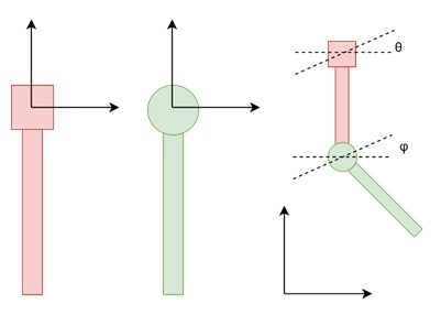
To better understand how scene graphs work, let us consider an example of a hinged pendulum. The pendulum consists of two parts: an upper part and a lower part, connected by a hinge.
Local and Global Transformations
Each part of the pendulum has its own local coordinate system. For example, if we want to move or rotate the upper part of the pendulum, we apply transformations like rotation and translation in its local coordinates.
Upper Pendulum
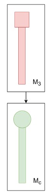
Rotate the upper pendulum by an angle θ (theta). Translate it to a position p. This transformation can be represented by a composite matrix, M3, which is the product of the rotation and translation matrices −
$$\mathrm{M_1 \:=\: \text{rotate }(\theta)}$$
$$\mathrm{M_2 \:=\: \text{translate }(p)}$$
$$\mathrm{M_3 \:=\: M_2\: \times\: M_1}$$
We apply this matrix to the upper pendulum, placing it correctly in the scene.
Managing the Lower Pendulum
The lower pendulum is more complicated. It is attached to the upper pendulum at a specific point, in the upper pendulums local coordinate system. The transformation for the lower pendulum involves −
- Rotating it by an angle φ (phi).
- Moving it so that its hinge aligns with the given point.
The composite transformation matrix for the lower pendulum is −
$$\mathrm{M_a \:=\: \text{rotate }(\varphi)}$$
$$\mathrm{M_b \:=\: \text{translate }(b)}$$
$$\mathrm{M_c \:=\: M_b\: \times \:M_a}$$
$$\mathrm{M_d \:=\: M_3\: \times \:M_c}$$
We apply Md to all the points of the lower pendulum. The lower pendulum moves along with the upper pendulum because its transformations are dependent on those of the upper part. This demonstrates the hierarchical nature of the scene graph.
Building the Scene Graph
In the case of the hinged pendulum, the scene graph helps to manage the relationship between the upper and lower pendulums. In the following figure shows the scene graph for this system.
In this graph, each transformation is represented as a node, and the hierarchy reflects how each objects transformation depends on its parent. The transformation for the lower pendulum depends on the upper pendulums transformation. Therefore, when the upper pendulum moves or rotates, the lower pendulum follows. This is automatically handled by the scene graph structure.
Scene Graphs in More Complex Scenes
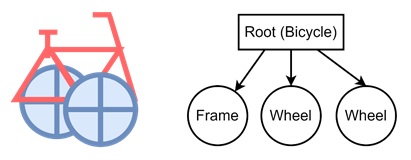
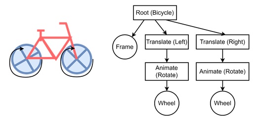
Consider a cycle has three components, the frame, and two wheels. The initial scene graph contains the root, then it is holding three children, frame, wheel, and wheel. From this basic graph we will increase this later on.
Now translate the first wheel to the left and second wheel to the right to form the proper bicycle. For that we need to translate block. After completing the bicycle, it will be ready for rotating wheels.
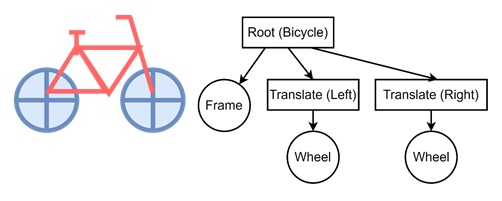
For rotation, we are adding the rotation nodes inside the scene graph. After translate it is animating for both the wheels. It is ready for moving bicycle now.
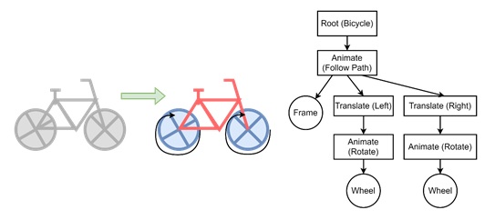
See in the following frame, it is following a path. For that we need the whole bicycle setup. After root, it is animating block then after that rest of the nodes are working like the same.
Recursive Traversal of a Scene Graph
Scene graphs are often traversed recursively. The function that performs this traversal operates on each node of the graph, applying the transformation matrices in the correct order. The basic steps of the traversal are as follows −
- Push the local transformation matrix onto the matrix stack.
- Draw the object using the composite matrix from the stack.
- Recursively traverse the child nodes of the current node.
- Pop the matrix after finishing with the current node.
Conclusion
In this chapter, we explained the basic concept of scene graphs in computer graphics. We started with the basics of scene graphs and how they manage transformations. Using the example of a hinged pendulum, we saw how transformations can be applied hierarchically.
We also looked at a more complex scene of bicycle system to show how scene graphs can manage many objects and transformations. Finally, we discussed matrix stacks and how they are used to efficiently implement scene graphs.