- Computer Graphics - Home
- Computer Graphics Basics
- Computer Graphics Applications
- Graphics APIs and Pipelines
- Computer Graphics Maths
- Sets and Mapping
- Solving Quadratic Equations
- Computer Graphics Trigonometry
- Computer Graphics Vectors
- Linear Interpolation
- Computer Graphics Devices
- Cathode Ray Tube
- Raster Scan Display
- Random Scan Device
- Phosphorescence Color CRT
- Flat Panel Displays
- 3D Viewing Devices
- Images Pixels and Geometry
- Color Models
- Line Generation
- Line Generation Algorithm
- DDA Algorithm
- Bresenham's Line Generation Algorithm
- Mid-point Line Generation Algorithm
- Circle Generation
- Circle Generation Algorithm
- Bresenham's Circle Generation Algorithm
- Mid-point Circle Generation Algorithm
- Ellipse Generation Algorithm
- Polygon Filling
- Polygon Filling Algorithm
- Scan Line Algorithm
- Flood Filling Algorithm
- Boundary Fill Algorithm
- 4 and 8 Connected Polygon
- Inside Outside Test
- 2D Transformation
- 2D Transformation
- Transformation Between Coordinate System
- Affine Transformation
- Raster Methods Transformation
- 2D Viewing
- Viewing Pipeline and Reference Frame
- Window Viewport Coordinate Transformation
- Viewing & Clipping
- Point Clipping Algorithm
- Cohen-Sutherland Line Clipping
- Cyrus-Beck Line Clipping Algorithm
- Polygon Clipping Sutherland–Hodgman Algorithm
- Text Clipping
- Clipping Techniques
- Bitmap Graphics
- 3D Viewing Transformation
- 3D Computer Graphics
- Parallel Projection
- Orthographic Projection
- Oblique Projection
- Perspective Projection
- 3D Transformation
- Rotation with Quaternions
- Modelling and Coordinate Systems
- Back-face Culling
- Lighting in 3D Graphics
- Shadowing in 3D Graphics
- 3D Object Representation
- Represnting Polygons
- Computer Graphics Surfaces
- Visible Surface Detection
- 3D Objects Representation
- Computer Graphics Curves
- Computer Graphics Curves
- Types of Curves
- Bezier Curves and Surfaces
- B-Spline Curves and Surfaces
- Data Structures For Graphics
- Triangle Meshes
- Scene Graphs
- Spatial Data Structure
- Binary Space Partitioning
- Tiling Multidimensional Arrays
- Color Theory
- Colorimetry
- Chromatic Adaptation
- Color Appearance
- Antialiasing
- Ray Tracing
- Ray Tracing Algorithm
- Perspective Ray Tracing
- Computing Viewing Rays
- Ray-Object Intersection
- Shading in Ray Tracing
- Transparency and Refraction
- Constructive Solid Geometry
- Texture Mapping
- Texture Values
- Texture Coordinate Function
- Antialiasing Texture Lookups
- Procedural 3D Textures
- Reflection Models
- Real-World Materials
- Implementing Reflection Models
- Specular Reflection Models
- Smooth-Layered Model
- Rough-Layered Model
- Surface Shading
- Diffuse Shading
- Phong Shading
- Artistic Shading
- Computer Animation
- Computer Animation
- Keyframe Animation
- Morphing Animation
- Motion Path Animation
- Deformation Animation
- Character Animation
- Physics-Based Animation
- Procedural Animation Techniques
- Computer Graphics Fractals
Perspective Ray Tracing in Computer Graphics
Ray tracing is used to create high-quality images of 3D scenes. It works by tracing rays of light to determine how they interact with the objects in a scene. An important aspect of ray tracing is perspective, which determines how 3D objects are viewed on a 2D screen. It helps create realistic images by making objects appear smaller as they get farther away from the camera.
In this chapter, we will explain the concept of perspective in ray tracing. We will also touch upon different types of projection and explain how perspective affects ray generation.
Understanding Perspective in Ray Tracing
The concept of perspective gives a sense of depth and makes images look natural. In ray tracing, perspective is used to determine how the rays are generated from the camera and how they travel through the scene.
Linear Perspective is the most common type of perspective used in computer graphics. It projects 3D objects onto a 2D image plane in such a way that straight lines in the scene become straight lines in the image. This type of perspective is used to produce realistic images because it mimics how we see the world.
Parallel Projection is another type of perspective, where 3D points are mapped to 2D by moving them along a projection direction until they hit the image plane. This type of projection is simpler but does not give a natural sense of depth.
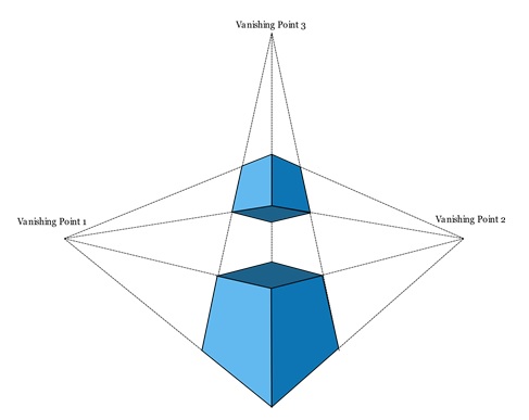
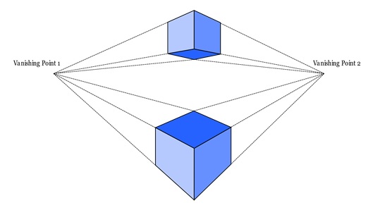
Perspective projection projects along lines that pass through a single viewpoint. This makes objects farther away appear smaller and parallel lines seem to meet at a point on the horizon, called the vanishing point.
Types of Projections in Ray Tracing
There are two main types of projections used in ray tracing: parallel projection and perspective projection. We know these from projection topics but let us see them in brief for ray tracing domain.
1. Parallel Projection
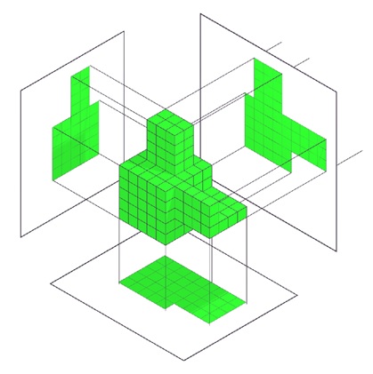
Parallel projection maps 3D points to a 2D plane using parallel lines. In this type of projection, objects do not appear smaller as they move farther from the viewpoint. This is because the projection lines remain parallel and do not converge, or converge at infinite distance.
There are two subtypes of parallel projections: Orthographic Projection and Oblique Projection.
Orthographic Projection
In orthographic projection, the projection lines are parallel and perpendicular to the image plane. This type of projection is useful when it is important to keep parallel lines parallel and maintain the true size of planar objects.
Oblique Projection
In oblique projection, the image plane is at an angle to the projection direction. This type of projection can show more of the object but does not appear realistic.
2. Perspective Projection
Perspective projection uses lines that pass through a single point, called the viewpoint. This makes objects farther away appear smaller. It also causes parallel lines to converge at the vanishing point on the horizon. This type of projection gives a realistic view of the scene because it mimics how we see things in the real world.
Perspective projection can be non-oblique, where a line drawn through the centre of the image is perpendicular to the image plane. This type of projection ensures that objects in the centre of the image are not distorted.
Computing Viewing Rays for Perspective
In ray tracing, viewing rays are used to get which objects are visible from the cameras viewpoint. The rays are generated based on the camera geometry, which includes the viewpoint and the image plane. The position and direction of each ray depend on the type of perspective being used.
For a perspective view, all rays originate from the same viewpoint but point in different directions. This means that the cameras viewpoint is fixed, and rays are sent out in various directions depending on the pixels location on the image plane. The distance from the cameras viewpoint to the image plane. It is known as image plane distance. This affects how the rays are generated and how the objects appear in the final image.
In a parallel projection, on the other hand, the rays start at different points on the image plane and all travel in the same direction. This makes the image look flat and less realistic because it does not provide a sense of depth.
Steps to Compute Viewing Rays
The steps to compute viewing rays are as follows −
- Determine the viewpoint, which is the origin of all rays in a perspective view.
- Compute the direction of each ray based on the pixel’s position on the image plane.
- Trace each ray into the scene to find the first object it intersects.
- Use the intersection point to determine the color of the pixel.
This process is repeated for each pixel in the image, resulting in a complete rendering of the scene.
Ray Generation in Perspective Projection
The process of generating rays in a perspective projection can be explained using a simple mathematical representation. A ray is defined by its origin and direction. In a perspective view, the origin is the viewpoint of the camera, and the direction is computed based on the pixels position on the image plane.
The formula for a ray can be written as −
$$\mathrm{p(t) \:=\: e \:+\: t(s \:-\: e)}$$
Where,
- p(t) is the position along the ray at a certain distance t.
- e is the origin of the ray (the camera’s viewpoint).
- s - e is the direction of the ray.
- t is a parameter that controls the distance along the ray.
By varying t, we can compute points along the ray and determine if it intersects any objects in the scene.
For a perspective view, the direction of each ray is different for every pixel. It can simulate how objects appear smaller as they get farther away. This gives a realistic effect and enhances the depth of the image.
Pros and Cons of Perspective in Ray Tracing
Perspective projection in ray tracing has several advantages −
- It creates realistic images by simulating how we see the world.
- Objects farther away appear smaller, giving a sense of depth.
- Parallel lines appear to meet at a vanishing point, creating a natural look.
However, perspective projection also has limitations −
- It requires more complex computations compared to parallel projection.
- Rays need to be traced in different directions, increasing the processing time.
- The resulting image can become distorted if the viewpoint or image plane is not chosen carefully.
Conclusion
In this chapter, we covered the concept of perspective in ray tracing. We discussed the importance of perspective in creating realistic images and explained the different types of projections used in ray tracing. We understood the process of computing viewing rays for perspective projection and provided an example to illustrate how perspective affects ray generation.