- Computer Graphics - Home
- Computer Graphics Basics
- Computer Graphics Applications
- Graphics APIs and Pipelines
- Computer Graphics Maths
- Sets and Mapping
- Solving Quadratic Equations
- Computer Graphics Trigonometry
- Computer Graphics Vectors
- Linear Interpolation
- Computer Graphics Devices
- Cathode Ray Tube
- Raster Scan Display
- Random Scan Device
- Phosphorescence Color CRT
- Flat Panel Displays
- 3D Viewing Devices
- Images Pixels and Geometry
- Color Models
- Line Generation
- Line Generation Algorithm
- DDA Algorithm
- Bresenham's Line Generation Algorithm
- Mid-point Line Generation Algorithm
- Circle Generation
- Circle Generation Algorithm
- Bresenham's Circle Generation Algorithm
- Mid-point Circle Generation Algorithm
- Ellipse Generation Algorithm
- Polygon Filling
- Polygon Filling Algorithm
- Scan Line Algorithm
- Flood Filling Algorithm
- Boundary Fill Algorithm
- 4 and 8 Connected Polygon
- Inside Outside Test
- 2D Transformation
- 2D Transformation
- Transformation Between Coordinate System
- Affine Transformation
- Raster Methods Transformation
- 2D Viewing
- Viewing Pipeline and Reference Frame
- Window Viewport Coordinate Transformation
- Viewing & Clipping
- Point Clipping Algorithm
- Cohen-Sutherland Line Clipping
- Cyrus-Beck Line Clipping Algorithm
- Polygon Clipping Sutherland–Hodgman Algorithm
- Text Clipping
- Clipping Techniques
- Bitmap Graphics
- 3D Viewing Transformation
- 3D Computer Graphics
- Parallel Projection
- Orthographic Projection
- Oblique Projection
- Perspective Projection
- 3D Transformation
- Rotation with Quaternions
- Modelling and Coordinate Systems
- Back-face Culling
- Lighting in 3D Graphics
- Shadowing in 3D Graphics
- 3D Object Representation
- Represnting Polygons
- Computer Graphics Surfaces
- Visible Surface Detection
- 3D Objects Representation
- Computer Graphics Curves
- Computer Graphics Curves
- Types of Curves
- Bezier Curves and Surfaces
- B-Spline Curves and Surfaces
- Data Structures For Graphics
- Triangle Meshes
- Scene Graphs
- Spatial Data Structure
- Binary Space Partitioning
- Tiling Multidimensional Arrays
- Color Theory
- Colorimetry
- Chromatic Adaptation
- Color Appearance
- Antialiasing
- Ray Tracing
- Ray Tracing Algorithm
- Perspective Ray Tracing
- Computing Viewing Rays
- Ray-Object Intersection
- Shading in Ray Tracing
- Transparency and Refraction
- Constructive Solid Geometry
- Texture Mapping
- Texture Values
- Texture Coordinate Function
- Antialiasing Texture Lookups
- Procedural 3D Textures
- Reflection Models
- Real-World Materials
- Implementing Reflection Models
- Specular Reflection Models
- Smooth-Layered Model
- Rough-Layered Model
- Surface Shading
- Diffuse Shading
- Phong Shading
- Artistic Shading
- Computer Animation
- Computer Animation
- Keyframe Animation
- Morphing Animation
- Motion Path Animation
- Deformation Animation
- Character Animation
- Physics-Based Animation
- Procedural Animation Techniques
- Computer Graphics Fractals
Orthographic Projection in Computer Graphics
In the previous chapter, we explained the concept of parallel projections. There are multiple such projections available in parallel projections; we can broadly divide them into orthographic and oblique projections. There are still some variations in orthographic projections.
In this chapter, we will see what orthographic projection is, how it works, and its different types. We will also cover the mathematical concepts behind orthographic projection, with examples for a better understanding.
Concept of Orthographic Projection
As we know from the overview, the orthographic projection is a method of representing three-dimensional objects in two-dimensional space or screen. Unlike perspective projection, which mimics how the human eye sees objects (with far objects appearing smaller). The orthographic projection preserves the true size of the objects, regardless of their distance from the viewer. This makes it useful in applications where accuracy and scale are crucial.
In an orthographic projection, parallel lines in the 3D space remain parallel in the 2D representation, without any distortion. The objects are projected along lines that are perpendicular to the projection plane.
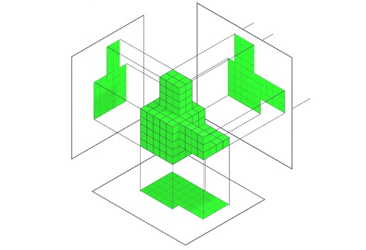
Example
Imagine we have a complex shape in 3D space. The 3D shape can be seen differently in different sides. The following figure will give you the insight of it.
Types of Orthographic Projection
There are three main types of orthographic projection, multi-view projection, axonometric projection, and oblique projection. Each type is used for different purposes and provides a unique way of representing 3D objects in 2D space. Here we will see orthographic Multiview and axonometric projections. In the next article we will cover oblique in detail.
Multi-View Orthographic Projection
Multi-view projection is the most commonly used type of orthographic projection. This is used in technical drawings and engineering designs. In this method, multiple views of the object are projected onto different planes. These views are typically −
- Front View
- Top View
- Side View
The above figure is showing these in action, in three panels.
Each of these views represents the object as seen from a different angle. The object is projected onto the projection plane along lines perpendicular to the plane. This ensures the true size and shape of each part of the object are preserved.
Axonometric Projection
On the other hand the axonometric projection is another type of orthographic projection, where the object is viewed from a skewed angle. Here it is allowing multiple faces of the object to be seen in a single image. The object is rotated along one or more axes. This is providing a view that shows the object's depth as well as its height and width. Axonometric projection is useful for visualizing 3D objects without the complexity of perspective distortion.
There are three main types of axonometric projection −
- Isometric Projection
- Dimetric Projection
- Trimetric Projection
Let us see these projections with examples a little
Isometric Projection
In isometric projection, the object is rotated so that the angles between the projection of the x, y, and z axes are all equal (typically 120 degrees). This results in a view where all three axes are equally foreshortened, giving a balanced view of the object. See the following example −
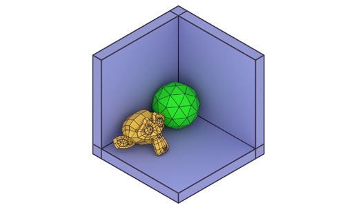
In isometric projection, all three dimensions (height, width, and depth) are represented equally, which gives a clear and simple visualization of the object. The scale remains consistent, and no perspective distortion occurs.
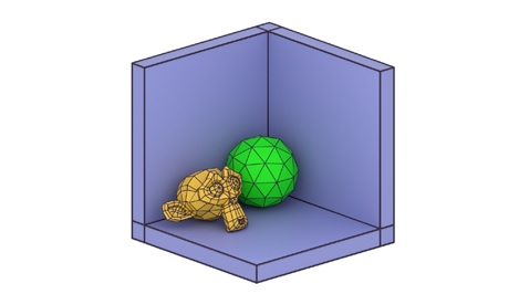
Dimetric Projection
In dimetric projection, two of the three axes are equally foreshortened, while the third axis is foreshortened by a different amount. This creates a view where two dimensions appear more balanced, while the third dimension is scaled differently. See the same example but in dimetric projection.
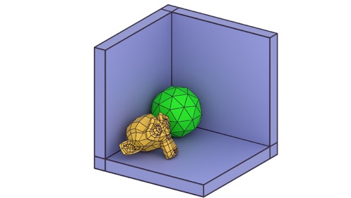
Trimetric Projection
In trimetric projection, all three axes are foreshortened by different amounts. This allows for a more flexible representation of the object, though it may be more challenging to interpret compared to isometric or dimetric projections. Let us see the example below −
Mathematical Representation of Orthographic Projection
Let us see the mathematical details of orthographic projection. Here only we see the basics of them, for each projections, angles will be different. We need matrices to represent the projections. These matrices are used to transform 3D coordinates into 2D coordinates on the projection plane.
Orthographic Projection Matrix
The general form of an orthographic projection matrix is as follows, with homogeneous coordinates.
$$\mathrm{P_{\text{ortho}} \:=\: \left[ \begin{array}{cccc} 1 & 0 & 0 & 0 \\ 0 & 1 & 0 & 0 \\ 0 & 0 & 0 & 0 \\ 0 & 0 & 0 & 1 \end{array} \right]}$$
This matrix projects the 3D object onto the 2D plane by ignoring the z-coordinate, which represents depth.
Scaling in Orthographic Projection
In addition to the basic projection matrix, scaling factors may be applied to adjust the view. The scaling factors Sx , Sy , and Sz can be used to scale the object along the x, y, and z axes, respectively. The projection matrix with scaling becomes −
$$\mathrm{P_{\text{scaled ortho}} \:=\: \left[ \begin{array}{cccc} S_x & 0 & 0 & 0 \\ 0 & S_y & 0 & 0 \\ 0 & 0 & S_z & 0 \\ 0 & 0 & 0 & 1 \end{array} \right]}$$
By applying this matrix, we can scale the object while projecting it onto the 2D plane.
Rotation in Orthographic Projection
In axonometric projection, where the object is rotated before projection, we use rotation matrices to rotate the object along the x, y, or z axes before applying the orthographic projection matrix. For example, the rotation matrix around the z-axis is given by −
$$\mathrm{R_Z(\theta) \:=\: \left[ \begin{array}{cccc} \cos \theta & -\sin \theta & 0 & 0 \\ \sin \theta & \cos \theta & 0 & 0 \\ 0 & 0 & 1 & 0 \\ 0 & 0 & 0 & 1 \end{array} \right]}$$
By multiplying the projection matrix by the rotation matrix, we can create rotated views of the object in axonometric projection.
Applications of Orthographic Projection
Orthographic projection is widely used in various fields of computer graphics, engineering, and design. Some common applications include −
- Technical Drawings − Orthographic projection is essential for creating accurate technical drawings and blueprints where precise measurements and dimensions are needed.
- Computer-Aided Design (CAD) − CAD software often uses orthographic projection to represent 3D models in 2D views.
- Game Development− In 2D and isometric games, orthographic projection is used to display objects without distortion.
- Architecture− Architects use orthographic projection to create accurate floor plans and building designs.
Conclusion
In this chapter, we covered the concept of orthographic projection in computer graphics. We explained how it works and its importance in representing 3D objects in a 2D space. We discussed the main two types of orthographic projection: multi-view projection and axonometric projection. Each of these projections serve different purposes and provide unique ways to represent 3D objects.
We also covered the mathematics behind orthographic projection, using projection matrices and transformations like scaling and rotation to accurately represent objects. Orthographic projection is widely used in fields like CAD, technical drawing, game development, and architecture, where accurate, distortion-free representation is crucial.