- Computer Graphics - Home
- Computer Graphics Basics
- Computer Graphics Applications
- Graphics APIs and Pipelines
- Computer Graphics Maths
- Sets and Mapping
- Solving Quadratic Equations
- Computer Graphics Trigonometry
- Computer Graphics Vectors
- Linear Interpolation
- Computer Graphics Devices
- Cathode Ray Tube
- Raster Scan Display
- Random Scan Device
- Phosphorescence Color CRT
- Flat Panel Displays
- 3D Viewing Devices
- Images Pixels and Geometry
- Color Models
- Line Generation
- Line Generation Algorithm
- DDA Algorithm
- Bresenham's Line Generation Algorithm
- Mid-point Line Generation Algorithm
- Circle Generation
- Circle Generation Algorithm
- Bresenham's Circle Generation Algorithm
- Mid-point Circle Generation Algorithm
- Ellipse Generation Algorithm
- Polygon Filling
- Polygon Filling Algorithm
- Scan Line Algorithm
- Flood Filling Algorithm
- Boundary Fill Algorithm
- 4 and 8 Connected Polygon
- Inside Outside Test
- 2D Transformation
- 2D Transformation
- Transformation Between Coordinate System
- Affine Transformation
- Raster Methods Transformation
- 2D Viewing
- Viewing Pipeline and Reference Frame
- Window Viewport Coordinate Transformation
- Viewing & Clipping
- Point Clipping Algorithm
- Cohen-Sutherland Line Clipping
- Cyrus-Beck Line Clipping Algorithm
- Polygon Clipping Sutherland–Hodgman Algorithm
- Text Clipping
- Clipping Techniques
- Bitmap Graphics
- 3D Viewing Transformation
- 3D Computer Graphics
- Parallel Projection
- Orthographic Projection
- Oblique Projection
- Perspective Projection
- 3D Transformation
- Rotation with Quaternions
- Modelling and Coordinate Systems
- Back-face Culling
- Lighting in 3D Graphics
- Shadowing in 3D Graphics
- 3D Object Representation
- Represnting Polygons
- Computer Graphics Surfaces
- Visible Surface Detection
- 3D Objects Representation
- Computer Graphics Curves
- Computer Graphics Curves
- Types of Curves
- Bezier Curves and Surfaces
- B-Spline Curves and Surfaces
- Data Structures For Graphics
- Triangle Meshes
- Scene Graphs
- Spatial Data Structure
- Binary Space Partitioning
- Tiling Multidimensional Arrays
- Color Theory
- Colorimetry
- Chromatic Adaptation
- Color Appearance
- Antialiasing
- Ray Tracing
- Ray Tracing Algorithm
- Perspective Ray Tracing
- Computing Viewing Rays
- Ray-Object Intersection
- Shading in Ray Tracing
- Transparency and Refraction
- Constructive Solid Geometry
- Texture Mapping
- Texture Values
- Texture Coordinate Function
- Antialiasing Texture Lookups
- Procedural 3D Textures
- Reflection Models
- Real-World Materials
- Implementing Reflection Models
- Specular Reflection Models
- Smooth-Layered Model
- Rough-Layered Model
- Surface Shading
- Diffuse Shading
- Phong Shading
- Artistic Shading
- Computer Animation
- Computer Animation
- Keyframe Animation
- Morphing Animation
- Motion Path Animation
- Deformation Animation
- Character Animation
- Physics-Based Animation
- Procedural Animation Techniques
- Computer Graphics Fractals
Oblique Projection in Computer Graphics
We explained orthographic projection and its two types in the previous chapter. There is another type known as oblique projection. Oblique projection provides a way to represent objects by displaying one face of the object in true size while the other faces are skewed.
In this chapter, we will see the concept of oblique projection, understand how it works, with examples and also explain the mathematics behind it. We will also discuss its applications and the advantages for a better understanding.
What is Oblique Projection?
Oblique projection is a type of parallel projection where the object is projected onto the 2D plane with the projection lines at an angle that is not perpendicular to the projection plane. So one face of the object (usually the front face) is shown in true size and shape, while the other faces of the object are skewed. This creates an illusion of depth.
Oblique projection is useful when we need to display multiple sides of an object in a single view. But we still want one face (usually the front) to appear in its true dimensions. It is a simple and effective method for representing 3D objects without introducing perspective distortion, making it popular in technical drawings, engineering, and architecture.
Types of Oblique Projection
There are two main types of oblique projection, but another type is also there. The major types are Cavalier projection and Cabinet projection. Both of these types differ in how the depth of the object is represented, and each has its own use cases.
1. Cavalier Projection
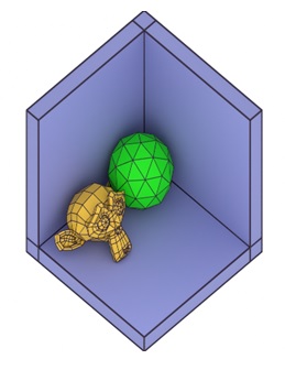
In Cavalier projection, the depth of the object is represented at full scale. It means the lines representing the depth of the object are drawn at their true length. The projection lines are typically drawn at a 45-degree angle to the projection plane. See the following example for a clear view −

Cavalier projection has the advantage of maintaining the correct proportions of the object, but it can make the object appear unrealistic because the depth is not reduced, leading to a stretched or exaggerated appearance.
2. Cabinet Projection
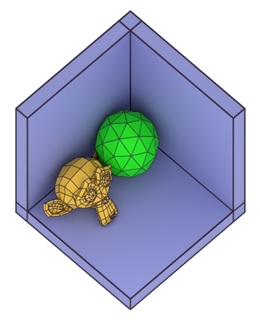
Cabinet projection is a more realistic version of oblique projection. In this method, the depth of the object is scaled to half its true length, while the front face remains in its true size and shape. Like Cavalier projection, the projection lines are drawn at an angle, usually 45 degrees, but the depth is reduced to give the object a more natural appearance. See the example −

Cabinet projection is widely used in engineering and architecture because it provides a clearer and more proportionate view of the object compared to Cavalier projection.
3. Military Projection
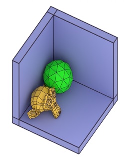
In military projection, the angles of the x-z and y-z axes are both set at 45°, while the x-y plane remains perpendicular with a 90° angle between the x and y axes. This means that the xy-plane is not skewed, but the entire projection is rotated by 45°, providing a view that emphasizes both the front and side views of an object.

In this projection, the z-axis is projected diagonally, and while the xy-plane maintains its true proportions, the depth (z) appears foreshortened, offering a clear representation of the objects dimensions without excessive distortion. Military projection is particularly useful in cartography and technical illustrations where both the vertical and horizontal planes need to be clearly represented.
Mathematical Representation of Oblique Projection
Let us see the oblique projections mathematically.
1. Projection Matrix for Oblique Projection
The general form of an oblique projection matrix can be written as −
$$\mathrm{P_{\text{oblique}} = \left[ \begin{array}{cccc} 1 & 0 & \alpha \cos \theta & 0 \\ 0 & 1 & \alpha \sin \theta & 0 \\ 0 & 0 & 0 & 0 \\ 0 & 0 & 0 & 1 \end{array} \right]}$$
Where,
- α is the scaling factor for the depth (1 for Cavalier projection, 0.5 for Cabinet projection).
- θ is the angle of projection (typically 45 degrees).
2. Coordinates Transformation
To project a 3D point (x, y, z) onto the 2D plane using oblique projection, the transformed 2D coordinates (x′, y′) are given by −
$$\mathrm{x' \:=\: x \:+\: \alpha \:\cdot\: z \:\cdot\: \cos \theta}$$
$$\mathrm{y' \:=\: y \:+\: \alpha \:\cdot\: z \:\cdot\: \sin \theta}$$
For Cavalier projection, where α=1\alpha = 1α=1, the full depth is represented, while for Cabinet projection, α=0.5, meaning the depth is halved.
Advantages of Oblique Projection
Following are the advantages of Oblique Projection –
- Simplicity − Oblique projection is easy to implement because the projection lines are drawn at a fixed angle and no complex calculations for perspective distortion are required. This makes it a simple and efficient method for visualizing 3D objects.
- Preservation of True Size − The front face of the object is displayed in its true size and shape, making it useful for technical drawings where accurate measurements are important.
- Quick Representation of Depth − By skewing the depth of the object, oblique projection provides a quick way to represent multiple faces of an object in a single view, without the need for multiple projections or views.
Limitations of Oblique Projection
Following are the limitations of Oblique Projection −
- Unrealistic Appearance (Cavalier Projection) − In Cavalier projection, the full-scale depth can make objects look unrealistic or stretched, especially when the depth is large. This limits its use in applications where realism is important.
- Lack of Perspective − Oblique projection does not mimic the way humans perceive depth. In real life, objects farther away from the viewer appear smaller, but in oblique projection, the depth is represented at a fixed angle and scale, making the image less natural compared to perspective projection.
- Distortion of Angles − Because the projection lines are not perpendicular to the projection plane, angles and shapes other than the front face can become distorted. This can make it harder to interpret the object's true shape, especially for more complex objects.
Applications of Oblique Projection
Oblique projection is widely used in several fields where simplicity and clear representation of objects are essential. Some common applications include −
- Technical Drawing − Oblique projection is often used in engineering drawings to represent objects clearly and accurately. The front face is shown in true size, which is crucial for technical specifications, while the depth provides additional information about the object's shape.
- Architecture − In architectural design, oblique projection is useful for representing buildings or rooms in a way that shows multiple sides at once. Cabinet projection, in particular, is often used because it provides a more realistic representation of depth.
- Computer-Aided Design (CAD) − Oblique projection is frequently used in CAD software to represent 3D models in 2D. It allows designers to view multiple sides of an object without the complexity of perspective projection, making it easier to work with technical drawings.
Conclusion
In this chapter, we explained the concept of oblique projection in computer graphics. We understood its working principles, types, and applications. We discussed Cavalier projection and Cabinet projection and also the Military projection.
Cavalier projection maintains full depth, while Cabinet projection halves the depth to create a more realistic view. We also looked at the mathematics behind oblique projection, including the projection matrix and the transformation of 3D coordinates into 2D space.