- Computer Graphics - Home
- Computer Graphics Basics
- Computer Graphics Applications
- Graphics APIs and Pipelines
- Computer Graphics Maths
- Sets and Mapping
- Solving Quadratic Equations
- Computer Graphics Trigonometry
- Computer Graphics Vectors
- Linear Interpolation
- Computer Graphics Devices
- Cathode Ray Tube
- Raster Scan Display
- Random Scan Device
- Phosphorescence Color CRT
- Flat Panel Displays
- 3D Viewing Devices
- Images Pixels and Geometry
- Color Models
- Line Generation
- Line Generation Algorithm
- DDA Algorithm
- Bresenham's Line Generation Algorithm
- Mid-point Line Generation Algorithm
- Circle Generation
- Circle Generation Algorithm
- Bresenham's Circle Generation Algorithm
- Mid-point Circle Generation Algorithm
- Ellipse Generation Algorithm
- Polygon Filling
- Polygon Filling Algorithm
- Scan Line Algorithm
- Flood Filling Algorithm
- Boundary Fill Algorithm
- 4 and 8 Connected Polygon
- Inside Outside Test
- 2D Transformation
- 2D Transformation
- Transformation Between Coordinate System
- Affine Transformation
- Raster Methods Transformation
- 2D Viewing
- Viewing Pipeline and Reference Frame
- Window Viewport Coordinate Transformation
- Viewing & Clipping
- Point Clipping Algorithm
- Cohen-Sutherland Line Clipping
- Cyrus-Beck Line Clipping Algorithm
- Polygon Clipping Sutherland–Hodgman Algorithm
- Text Clipping
- Clipping Techniques
- Bitmap Graphics
- 3D Viewing Transformation
- 3D Computer Graphics
- Parallel Projection
- Orthographic Projection
- Oblique Projection
- Perspective Projection
- 3D Transformation
- Rotation with Quaternions
- Modelling and Coordinate Systems
- Back-face Culling
- Lighting in 3D Graphics
- Shadowing in 3D Graphics
- 3D Object Representation
- Represnting Polygons
- Computer Graphics Surfaces
- Visible Surface Detection
- 3D Objects Representation
- Computer Graphics Curves
- Computer Graphics Curves
- Types of Curves
- Bezier Curves and Surfaces
- B-Spline Curves and Surfaces
- Data Structures For Graphics
- Triangle Meshes
- Scene Graphs
- Spatial Data Structure
- Binary Space Partitioning
- Tiling Multidimensional Arrays
- Color Theory
- Colorimetry
- Chromatic Adaptation
- Color Appearance
- Antialiasing
- Ray Tracing
- Ray Tracing Algorithm
- Perspective Ray Tracing
- Computing Viewing Rays
- Ray-Object Intersection
- Shading in Ray Tracing
- Transparency and Refraction
- Constructive Solid Geometry
- Texture Mapping
- Texture Values
- Texture Coordinate Function
- Antialiasing Texture Lookups
- Procedural 3D Textures
- Reflection Models
- Real-World Materials
- Implementing Reflection Models
- Specular Reflection Models
- Smooth-Layered Model
- Rough-Layered Model
- Surface Shading
- Diffuse Shading
- Phong Shading
- Artistic Shading
- Computer Animation
- Computer Animation
- Keyframe Animation
- Morphing Animation
- Motion Path Animation
- Deformation Animation
- Character Animation
- Physics-Based Animation
- Procedural Animation Techniques
- Computer Graphics Fractals
Transparency and Refraction in Ray Tracing
Transparency and Refractions play an important role in rendering materials like glass, water, and diamonds. These effects give objects their unique appearance. In this chapter, we will see how transparency and refraction are handled in ray tracing.
Transparency in Ray Tracing
Ray tracing works by simulating the behavior of light as it interacts with objects in a scene. It calculates reflections, shadows, and other lighting effects by tracing the path of rays from the camera to light sources.
Transparency refers to how much light passes through a material. In ray tracing, transparency is simulated by allowing some rays to pass through an object instead of reflecting off it.
When light passes through transparent materials like glass or water, the light rays bend, causing what we know as refraction. This effect occurs because light travels at different speeds in different materials.
For example, when light moves from air (which has a refractive index of 1.0) into water (which has a refractive index of 1.33), it bends according to Snell's Law. The refractive index measures how much light slows down in a medium compared to a vacuum.
Snell's Law and Refraction
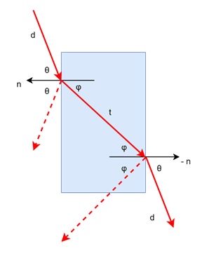
Refraction is the bending of light as it passes from one material to another. Snell's Law is a fundamental equation in ray tracing that describes how light bends. It states:
$$\mathrm{n \:\sin\: \theta \:=\: n_t \:\sin\: \varphi}$$
Where,
- n is the refractive index of the first material
- θ is the angle of the incoming ray
- nt is the refractive index of the second material
- is the angle of the refracted ray
In simple terms, when light hits a surface, part of it is reflected, and part of it is transmitted into the material, changing its direction. The amount of bending depends on the refractive indices of the two materials.
Refractive Indices
From the following list, you can observe how materials like diamond have a much higher refractive index than air, making light bend sharply when passing through them.
- Air: 1.00
- Water: 1.33-1.34
- Window Glass: 1.51
- Optical Glass: 1.49-1.92
- Diamond: 2.42
Mathematics behind Refraction
To calculate the refraction, it needs determining the angles of incidence and refraction using trigonometry. Since computing sines and cosines can be complex, a more convenient approach uses the relationship −
$$\mathrm{\cos^2 \varphi \:=\: 1 \:-\: \frac{n^2}{n_t^2} \left( 1 \:-\: \cos^2 \theta \right)}$$
In this formula, θ is the angle between the incident ray and the surface normal. If the refractive indices are reversed, so are the angles θ and . This equation helps ray tracing programs calculate how light bends when it passes through objects.
Refraction Vector
To convert these angles into a 3D vector for use in ray tracing, we define the transmission vector t as −
$$\mathrm{t \:=\: \sin \varphi \:\cdot\: b \:-\: \cos \varphi \:\cdot\: n}$$
Where, b is a basis vector and n is the surface normal.
This vector represents the direction in which the light travels after refraction.
Total Internal Reflection
From the class of physics we know another important thing called the internal total reflection. Sometimes, light doesn't refract but instead reflects entirely inside the material. This phenomenon is known as total internal reflection.
Total Internal Reflection occurs when light tries to move from a material with a high refractive index to one with a lower index at a steep angle. If the angle is too steep, the light reflects back into the material rather than passing through. This effect is commonly seen in diamonds and glass, giving them their sparkling, reflective appearance.
Reflectivity and Fresnel Equations
For ray tracing we must understand the physics. Another important equation that is needed is the Fresnel equations. These equations describe how much light is reflected and how much is refracted when it hits a surface.
The amount of reflection depends on the angle of incidence. As the angle increases, more light is reflected.
A simplified version of this equation, called the Schlick approximation, is often used in ray tracing −
$$\mathrm{R(\theta) \:=\: R_0 \:+\: (1 \:-\: R_0)(1 \:-\: \cos \theta)^5}$$
Where R0 is the reflectance at normal incidence, calculated as −
$$\mathrm{R_0 \:=\: \left( \frac{n_t \:-\: 1}{n_t \:+\: 1} \right)^2}$$
This approximation allows for more efficient calculations without significantly affecting visual quality.
Attenuation and Beers Law
From physics we know that transparent materials also filter light. This changes its intensity and color as it passes through. This filtering effect is governed by Beer’s Law. The law states that the intensity of light decreases as it travels through a material.
The formula for Beer’s Law is −
$$\mathrm{I(s) \:=\: I_0 e^{-\ln(a) s}}$$
Where,
- I(s) is the intensity at a distance s,
- I0 is the original intensity,
- a is the attenuation constant, which depends on the material.
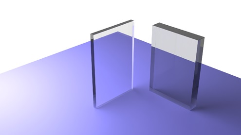
In computer graphics, this equation is often adjusted by trial and error to achieve the desired appearance. The effects of Beer’s Law are visible when glass takes on a tint, like the green hue often seen in thick panes of glass.
Implementing Transparency in Ray Tracing
To implement transparency and refraction in ray tracing, the renderer must calculate when a ray is entering or exiting a transparent object. Usually, objects are assumed to be in the air with a refractive index of 1.0, and the surface normals point outward from the object. The renderer then calculates whether to reflect or refract the ray using the formulas discussed above.
When a ray refracts, its color is calculated based on how much light passes through the object and how much is reflected. The program uses these values to create realistic renderings of transparent materials.
Let us see a simple code for transparency in ray tracing −
if (p is on a dielectric) then
  r = reflect(d, n)
  if (d  n < 0) then
    refract(d, n, n, t)
    c = d  n
  else
    kr = exp(art)
    kg = exp(agt)
    kb = exp(abt)
  if refract(d, n, 1/n, t) then
    c = t  n
This code handles the calculation of reflections and refractions. This ensures that transparent objects behave realistically when rendered.
Conclusion
In this chapter, we explained the basics of transparency and refraction in ray tracing. We also covered the key principles of Snell's Law, total internal reflection, Fresnel equations, and Beers Law. We explored how ray tracing simulates the behavior of light as it passes through materials like glass and water, creating realistic renderings of transparent objects.
Through examples and mathematical explanations, we have shown how these concepts are implemented in ray tracing software.