- Computer Graphics - Home
- Computer Graphics Basics
- Computer Graphics Applications
- Graphics APIs and Pipelines
- Computer Graphics Maths
- Sets and Mapping
- Solving Quadratic Equations
- Computer Graphics Trigonometry
- Computer Graphics Vectors
- Linear Interpolation
- Computer Graphics Devices
- Cathode Ray Tube
- Raster Scan Display
- Random Scan Device
- Phosphorescence Color CRT
- Flat Panel Displays
- 3D Viewing Devices
- Images Pixels and Geometry
- Color Models
- Line Generation
- Line Generation Algorithm
- DDA Algorithm
- Bresenham's Line Generation Algorithm
- Mid-point Line Generation Algorithm
- Circle Generation
- Circle Generation Algorithm
- Bresenham's Circle Generation Algorithm
- Mid-point Circle Generation Algorithm
- Ellipse Generation Algorithm
- Polygon Filling
- Polygon Filling Algorithm
- Scan Line Algorithm
- Flood Filling Algorithm
- Boundary Fill Algorithm
- 4 and 8 Connected Polygon
- Inside Outside Test
- 2D Transformation
- 2D Transformation
- Transformation Between Coordinate System
- Affine Transformation
- Raster Methods Transformation
- 2D Viewing
- Viewing Pipeline and Reference Frame
- Window Viewport Coordinate Transformation
- Viewing & Clipping
- Point Clipping Algorithm
- Cohen-Sutherland Line Clipping
- Cyrus-Beck Line Clipping Algorithm
- Polygon Clipping Sutherland–Hodgman Algorithm
- Text Clipping
- Clipping Techniques
- Bitmap Graphics
- 3D Viewing Transformation
- 3D Computer Graphics
- Parallel Projection
- Orthographic Projection
- Oblique Projection
- Perspective Projection
- 3D Transformation
- Rotation with Quaternions
- Modelling and Coordinate Systems
- Back-face Culling
- Lighting in 3D Graphics
- Shadowing in 3D Graphics
- 3D Object Representation
- Represnting Polygons
- Computer Graphics Surfaces
- Visible Surface Detection
- 3D Objects Representation
- Computer Graphics Curves
- Computer Graphics Curves
- Types of Curves
- Bezier Curves and Surfaces
- B-Spline Curves and Surfaces
- Data Structures For Graphics
- Triangle Meshes
- Scene Graphs
- Spatial Data Structure
- Binary Space Partitioning
- Tiling Multidimensional Arrays
- Color Theory
- Colorimetry
- Chromatic Adaptation
- Color Appearance
- Antialiasing
- Ray Tracing
- Ray Tracing Algorithm
- Perspective Ray Tracing
- Computing Viewing Rays
- Ray-Object Intersection
- Shading in Ray Tracing
- Transparency and Refraction
- Constructive Solid Geometry
- Texture Mapping
- Texture Values
- Texture Coordinate Function
- Antialiasing Texture Lookups
- Procedural 3D Textures
- Reflection Models
- Real-World Materials
- Implementing Reflection Models
- Specular Reflection Models
- Smooth-Layered Model
- Rough-Layered Model
- Surface Shading
- Diffuse Shading
- Phong Shading
- Artistic Shading
- Computer Animation
- Computer Animation
- Keyframe Animation
- Morphing Animation
- Motion Path Animation
- Deformation Animation
- Character Animation
- Physics-Based Animation
- Procedural Animation Techniques
- Computer Graphics Fractals
Constructive Solid Geometry in Ray Tracing
Constructive Solid Geometry (CSG) is used for creating complex shapes using simple geometric primitives. Ray tracing can be used with CSG to produce realistic and detailed 3D objects.
In this chapter, we will see the basics of Constructive Solid Geometry, its operations, and how it is implemented in ray tracing.
What is Constructive Solid Geometry?
Constructive Solid Geometry (CSG) is a modelling technique that combines simple shapes to form complex 3D objects. These shapes are known as primitives, like spheres, cubes, cylinders, and other basic geometries. CSG operations such as union, intersection, and difference are applied to these primitives to create more complex models.
In ray tracing, CSG is used to generate intricate shapes by combining different primitives. The process is similar to combining clay models to form new structures. Instead of manipulating vertices or faces directly, CSG allows you to focus on the logical combination of shapes.
Example of CSG Operations
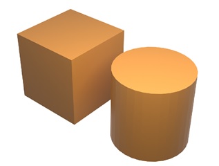
Assume we have two objects as follows −
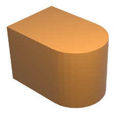
Union − Combines two or more objects into a single shape.
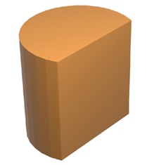
Intersection − Creates a new shape from the overlapping parts of objects.
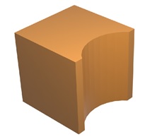
Difference − Subtracts one object from another, creating a cut-out or hole.
Or,
Understanding Set Operations in CSG
In the above examples, we have seen the set operations with examples. CSG operations can be thought of these set operations. For example, consider a cylinder C and a cube Cu.
- The union operation C∪ Cu creates a shape like D shaped object. It includes all the points that are in either the cube or the cylinder.
- The intersection operation C ∩ Cu includes only those points that are in both shapes.
- The difference operation C − Cu includes all points in the cylinder that are not in the cube.
Implementing CSG in Ray Tracing
After understanding the operations, next part is understanding how ray tracing can do this. Constructive Solid Geometry is implemented by finding all intersections of a ray with a model rather than just the closest intersection. This approach helps to perform set operations directly on the rays as they interact with the model.
For example, when a ray hits a sphere, it might intersect at two points, t = 1 and t = 2. The ray is considered to be inside the sphere for t∈ [1, 2]. In the context of CSG, we think of this interval as representing the ray being inside the sphere. We can compute these "inside intervals" for all surfaces and perform set operations on those intervals.
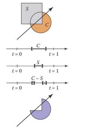
The concept is illustrated in the above figure, where the hit intervals are processed to show the ray interacting with the composite object. For a difference operation like C S, the ray might be inside the circle and outside the square. This method helps to create precise intersections for complex shapes.
CSG and Ray Intersections
The CSG intersection routine must maintain a list of intervals. When the first hit point is determined, the material property and surface normal are assigned to that point. The list of intervals helps manage multiple intersections, ensuring the correct geometry is rendered.
Precision and Robustness in CSG
One challenge with Constructive Solid Geometry is maintaining precision during set operations. Small inaccuracies in computing intersections can lead to visual artifacts.
For example, if two objects are very close or about each other, slight errors can cause gaps or overlaps. To address this issue, it is needed to implement a tolerance value to eliminate any intervals whose thickness is below a certain threshold.
This ensures that the resulting shape is robust and visually accurate. Eliminating tiny intervals helps avoid rendering errors and makes the CSG model more reliable. Proper handling of precision issues is crucial when dealing with complex models that involve multiple intersections and operations.
Managing Intersections
The intersection routine must also pay attention to precision issues when combining shapes. If a sphere and a cube are very close, the routine must handle the intersection points carefully to avoid inconsistencies. This process may involve adjusting the tolerance or using special algorithms to smooth out the boundaries.
Advantages of CSG in Ray Tracing
Constructive Solid Geometry offers several advantages in ray tracing −
- Simpler Intersection Calculations − Using CSG, complex shapes can be broken down into simpler intersections. For example, a complex object like a car can be represented as a combination of basic shapes like cylinders and boxes. This makes intersection routines easier to manage.
- Efficient Memory Usage − By using CSG, multiple transformed objects can share the same base geometry. For example, a traffic jam of cars can use the same base model for individual cars. This reduces the memory needed to store multiple instances of complex models.
- Flexible Model Creation − CSG allows designers to create flexible and dynamic models. Instead of storing every detail, designers can create new models by combining or altering existing shapes. This approach simplifies the modelling process and enables creative designs.
Conclusion
In this chapter, we explained the concept of Constructive Solid Geometry in ray tracing. We covered the basic operations of CSG, including union, intersection, and difference, and how these are implemented in ray tracing.
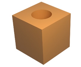
We discussed how CSG helps create complex shapes using simple primitives and how precision issues can be managed. By maintaining a list of intervals and carefully managing intersections, CSG allows for efficient and flexible model creation. We also looked at an example where a sphere is subtracted from a cube, showing how CSG simplifies the modelling process.