- Computer Graphics - Home
- Computer Graphics Basics
- Computer Graphics Applications
- Graphics APIs and Pipelines
- Computer Graphics Maths
- Sets and Mapping
- Solving Quadratic Equations
- Computer Graphics Trigonometry
- Computer Graphics Vectors
- Linear Interpolation
- Computer Graphics Devices
- Cathode Ray Tube
- Raster Scan Display
- Random Scan Device
- Phosphorescence Color CRT
- Flat Panel Displays
- 3D Viewing Devices
- Images Pixels and Geometry
- Color Models
- Line Generation
- Line Generation Algorithm
- DDA Algorithm
- Bresenham's Line Generation Algorithm
- Mid-point Line Generation Algorithm
- Circle Generation
- Circle Generation Algorithm
- Bresenham's Circle Generation Algorithm
- Mid-point Circle Generation Algorithm
- Ellipse Generation Algorithm
- Polygon Filling
- Polygon Filling Algorithm
- Scan Line Algorithm
- Flood Filling Algorithm
- Boundary Fill Algorithm
- 4 and 8 Connected Polygon
- Inside Outside Test
- 2D Transformation
- 2D Transformation
- Transformation Between Coordinate System
- Affine Transformation
- Raster Methods Transformation
- 2D Viewing
- Viewing Pipeline and Reference Frame
- Window Viewport Coordinate Transformation
- Viewing & Clipping
- Point Clipping Algorithm
- Cohen-Sutherland Line Clipping
- Cyrus-Beck Line Clipping Algorithm
- Polygon Clipping Sutherland–Hodgman Algorithm
- Text Clipping
- Clipping Techniques
- Bitmap Graphics
- 3D Viewing Transformation
- 3D Computer Graphics
- Parallel Projection
- Orthographic Projection
- Oblique Projection
- Perspective Projection
- 3D Transformation
- Rotation with Quaternions
- Modelling and Coordinate Systems
- Back-face Culling
- Lighting in 3D Graphics
- Shadowing in 3D Graphics
- 3D Object Representation
- Represnting Polygons
- Computer Graphics Surfaces
- Visible Surface Detection
- 3D Objects Representation
- Computer Graphics Curves
- Computer Graphics Curves
- Types of Curves
- Bezier Curves and Surfaces
- B-Spline Curves and Surfaces
- Data Structures For Graphics
- Triangle Meshes
- Scene Graphs
- Spatial Data Structure
- Binary Space Partitioning
- Tiling Multidimensional Arrays
- Color Theory
- Colorimetry
- Chromatic Adaptation
- Color Appearance
- Antialiasing
- Ray Tracing
- Ray Tracing Algorithm
- Perspective Ray Tracing
- Computing Viewing Rays
- Ray-Object Intersection
- Shading in Ray Tracing
- Transparency and Refraction
- Constructive Solid Geometry
- Texture Mapping
- Texture Values
- Texture Coordinate Function
- Antialiasing Texture Lookups
- Procedural 3D Textures
- Reflection Models
- Real-World Materials
- Implementing Reflection Models
- Specular Reflection Models
- Smooth-Layered Model
- Rough-Layered Model
- Surface Shading
- Diffuse Shading
- Phong Shading
- Artistic Shading
- Computer Animation
- Computer Animation
- Keyframe Animation
- Morphing Animation
- Motion Path Animation
- Deformation Animation
- Character Animation
- Physics-Based Animation
- Procedural Animation Techniques
- Computer Graphics Fractals
Phong Shading in Computer Graphics
Phong shading is a commonly used shading model that provides a way to simulate the shiny highlights on objects like polished floors, painted surfaces, and even whiteboards. It gives more visual depth by including the reflection of light. It makes surfaces appear glossy or metallic.
In this chapter, we will see the basics of Phong shading, and see its key concepts, and provide a detailed example for a better understanding.
What is Phong Shading?
Phong shading is different from diffuse shading. It is designed for handling surfaces that are not entirely matte. It is used when an object has highlights or bright spots where the light reflects most directly. Examples include polished tiles, glossy paint, etc. These highlights change as the viewpoint moves, which makes the surface appear realistic.
To simulate this effect, Phong shading introduces a new vector called e, which points toward the viewer or eye. The highlights on a surface are reflections of the light source. Often, these reflections appear blurred. This means the light bounces off the surface and creates a soft, glowing effect rather than a sharp spot.
Phong Lighting Model
In Phong shading, we target to add a fuzzy spot to represent the light source reflecting off the surface. The reflection happens when the direction toward the eye (e) lines up with the natural reflection direction (r). When this alignment occurs, the eye will see the highlight clearly.
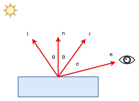
The geometry for this reflection is shown in the above figure. In simpler terms, we want to place the bright spot at the point where the light reflection meets the viewer’s eye.
For example, imagine a polished floor with a bright light source above. As we move around, the spot of light moves too, appearing more or less intense depending on our position relative to the reflection.
To mathematically represent this, we use the cosine of the angle between the reflection vector r and the vector pointing toward the eye e −
$$\mathrm{c \:=\: cl \:\cdot\: (e\: \cdot\: r)}$$
Here, cl represents the color of the light source. In this simple model it has a problem: the dot product between e and r can be negative when the vectors point in opposite directions. To solve this, we can introduce a condition that sets the color to zero when the dot product is negative. This prevents unrealistic lighting effects when the reflection is not visible to the viewer.
Another issue with this simple equation is that the highlight might appear too large. To make the highlight more realistic, we narrow it down by raising the cosine result to a power −
$$\mathrm{c \:=\: cl \:\cdot\: \max(0,\: e\: \cdot\: r)^p}$$
In this equation, p is called the Phong exponent. This exponent controls the size of the highlight. A higher value of p creates a smaller, sharper highlight, which is closer to how real-world reflections appear.
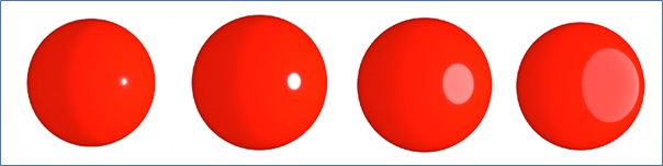
Consider the above shiny sphere under a bright light. If the Phong exponent is small, the highlight will spread out over a large area, making the surface look duller. Increasing the exponent makes the highlight smaller and more concentrated, giving the surface a shiny, reflective appearance.
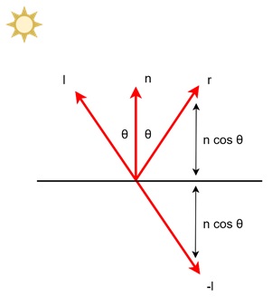
Calculating the Reflection Vector
To implement Phong shading, we need to compute the reflection vector (r). This vector represents the direction in which light reflects off the surface. The calculation is based on the direction of the light source (l) and the surface normal (n).
The reflection vector can be found using the following formula −
$$\mathrm{r \:=\: -l \:+\: 2 (l \:\cdot\: n) n}$$
This formula reflects the light vector l around the normal vector n. The dot product l . n helps compute the angle between these two vectors. For example, imagine a mirror lying flat on a table, with a flashlight shining directly down on it.
The normal vector n points straight up, and the light vector l points down. The reflection vector r will point straight back toward the light source, following the rule of reflection.
Using the Halfway Vector
An alternative to using the reflection vector is to compute the halfway vector (h). This method simplifies the shading model because it eliminates the need to check for negative values in the dot product.
The halfway vector is the direction halfway between the light vector l and the eye vector e −
$$\mathrm{h \:=\: \frac{e \:+\: l}{\left| e \:+\: l \right|}}$$
Here, h is a normalized vector (its length is one) that points between the light and the viewer. The idea is that the highlight will appear when the halfway vector aligns with the surface normal n.
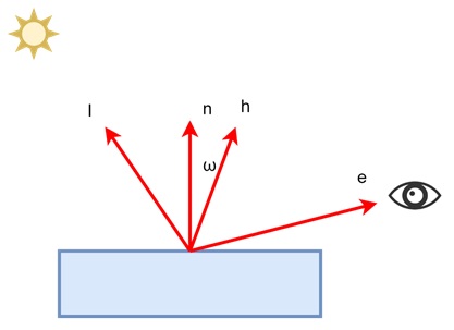
This approach gives a slightly different result from using the reflection vector, but it has a significant advantage: it avoids negative values in the calculations, making it more computationally efficient.
For example, think of a light source shining on a curved object like a ball. The halfway vector method helps calculate the soft highlights on the surface. As you move around the object, the halfway vector changes, allowing the highlights to move with the light.
Combining Diffuse and Phong Shading
Phong shading works best when combined with diffuse shading to give a surface both highlights and overall lighting. The equation for combining these two shading techniques is as follows −
$$\mathrm{c \:=\: cr \:\cdot\: \left( ca \:+\: cl \:\cdot\: \max(0,\: n \:\cdot\: l) \right) \:+\: cl \:\cdot\: \max(0,\: h \:\cdot\: n)^p}$$
Here, cr represents the surface's diffuse reflectance, ca represents ambient light, and cl is the color of the light. This equation shows both diffuse shading and specular highlights (Phong shading) contribute to the final appearance of the object. We can understand through an example of polished whiteboard.
The diffuse shading will handle the general brightness of the board, while Phong shading will add the sharp, bright highlights where the light reflects off the surface.
Conclusion
In this chapter, we presented the basic concept of Phong shading and its importance in surface shading. We explained Phong shading's ability to handle shiny surfaces with highlights. We discussed the Phong lighting model, including the calculation of the reflection vector and the use of the halfway vector as an alternative.
We also understood how to combine Phong shading with diffuse shading to give surfaces both highlights and overall brightness. Finally, we looked at how the Phong exponent controls the sharpness of the highlights and how it can be used to simulate different materials.